This thread has been locked.

If you have a related question, please click the "Ask a related question" button in the top right corner. The newly created question will be automatically linked to this question.

CC2650: Get wrong magnetic data from sensor

Part Number: CC2650

Hi every one,

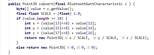
I get magnetic data from sensor CC2650 to my android phone using formula from  TI wiki (http://processors.wiki.ti.com/index.php/CC2650_SensorTag_User%27s_Guide#Movement_Sensor)


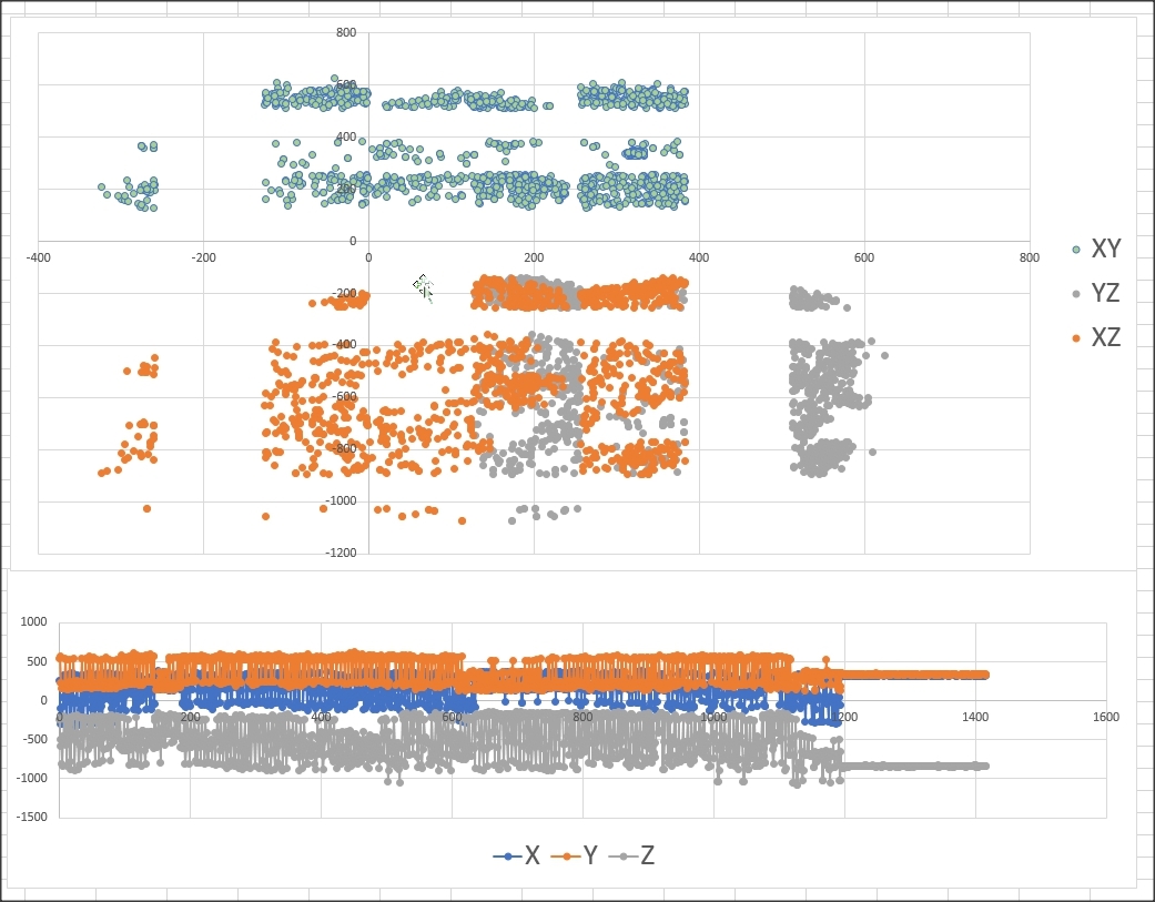
I waved the sensor in the figure 8 motion then plotted data to scatter chart for calibration as bellow but It seem that result was unexpected.
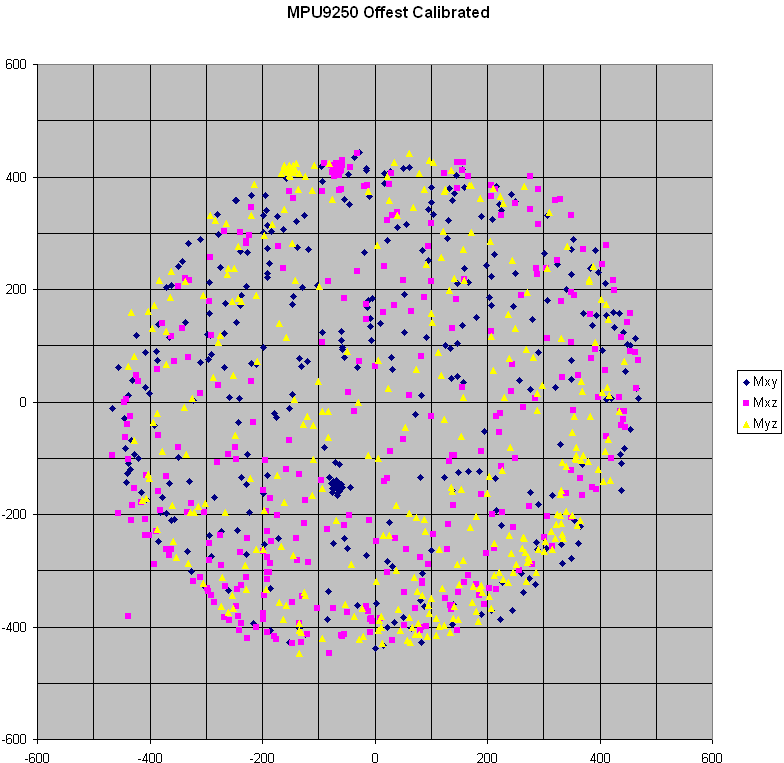
It should be 3 circular shapes before calibrate but it was not. I tried with 2 other sensor but I got the same result.
https://github.com/kriswiner/MPU6050/wiki/Simple-and-Effective-Magnetometer-Calibration

Please help me ! Sorry about my English.Thanks so much !!!


  • Hi Dung,

    Are you looking at the SensorMpu9250.c file include in the sensortag application? This is the filepath to it: tirtos_cc13xx_cc26xx_2_20_01_08\products\tidrivers_cc13xx_cc26xx_2_20_01_10\packages\ti\mw\sensors

    This provides a driver for the magnetometer that you should be able to plug into your application.

    More specifically, it looks like you are missing parts of the data conversion in your function.

    Here's the relevant snippet from the driver file:

    // Burst read of all compass values + ST2 register
                if (SensorI2C_readReg(MAG_XOUT_L, &rawData[0],7))
                {
                    val = rawData[6]; // ST2 register
    
                    // Check if magnetic sensor overflow set, if not report data
                    if(!(val & 0x08))
                    {
                        // Turn the MSB and LSB into a signed 16-bit value,
                        // data stored as little Endian
                        data[0] = ((int16_t)rawData[1] << 8) | rawData[0];
                        data[1] = ((int16_t)rawData[3] << 8) | rawData[2];
                        data[2] = ((int16_t)rawData[5] << 8) | rawData[4];
    
                        // Sensitivity adjustment
                        data[0] = data[0] * calX >> 8;
                        data[1] = data[1] * calY >> 8;
                        data[2] = data[2] * calZ >> 8;
                    }

    I highly suggest using the driver either as a reference or directly in your project.

    -Sy Su

  • Hi Sy Su, Thank you so much!

    I am developing on Android, so I can't use this driver directly.

    Sy Su said:
    More specifically, it looks like you are missing parts of the data conversion in your function.

    Do you mean calibration values CalX,CalY,CalZ ? I have a trouble when I try to read these values. Which function is equal to sensorReadReg() in java ?

    static void sensorMagInit(void)
    {
      uint8_t rawData[3];
    
      sensorMpu9250SetBypass();
    
      SENSOR_SELECT_MAG();
    
      // Enter Fuse ROM access mode
      val = 0x0F;
      sensorWriteReg(MAG_CNTL, &val, 1);
      delay_ms(10);
    
      // Get calibration data
      sensorReadReg(MAG_ASAX, &rawData[0], 3);  // Read the x-, y-, and z-axis calibration values
      calX =  (float)(rawData[0] - 128)/256.0 + 1.0;   // Return x-axis sensitivity adjustment values, etc.
      calY =  (float)(rawData[1] - 128)/256.0 + 1.0;
      calZ =  (float)(rawData[2] - 128)/256.0 + 1.0;
    
      // Turn off the sensor again
      val = 0x00;
      sensorWriteReg(MAG_CNTL, &val, 1);
      delay_ms(10);
    
      SENSOR_DESELECT();
    }

  • Hi Dung,

    Yes, I'm referring to the sensitivity adjustment.
    The sensorReadReg is an I2C read function that should be happening on the device (CC2650), not in Java/on the Android phone.
    Are you sending the data to the phone with it converted already? Or are you sending the raw data to the phone and converting it on the phone?

    -Sy Su
  • Now, I am using factory firmware to send the raw data to my phone then use "decode function" as I mentioned above to convert ...

    So, what should I do ? Modify firmware then upload to sensor ?

    Could you help me ? I have not experienced in sensor :)

  • Dung,

    I would suggest to get the data and convert it on the device.
    This will involve modifying the device's firmware.
    However, this should be rather simple since you can now use the pre-written driver (SensorMpu9250.c ) in your project and the data will be converted correctly.

    If you don't want to do this and just do the data conversion on the phone, you will need to get CalX, CalY, CalZ using the CC2650 and also send those values to the phone. Now that the phone has those calibration values, you will be able to convert the data properly by following the similar process in the code snippet I provided earlier.

    -Sy Su
  • Sy Su said:
    you will need to get CalX, CalY, CalZ using the CC2650 and also send those values to the phone

    Could you tell me more detail about this method? How can I get these values from my sensor?

    Thank you!

  • Dung,

    I highly suggest you look at the SensorMpu9250.c driver file. This will help answer your questions.

    Now, if you open SensorMpu9250.c and check the sensorMagInit function, you will see how calX, calY, calZ is obtained. It gets the calibration data by doing an I2C burst read (3 bytes) on the MAG_ASAX register and stores it in the rawData array. Then from there calX, calY, calZ is derived as so:

    // Get calibration data
    if (SensorI2C_readReg(MAG_ASAX, &rawData[0], 3))
    {
       // Return x-axis sensitivity adjustment values, etc.
       calX =  (int16_t)rawData[0] + 128;
       calY =  (int16_t)rawData[1] + 128;
       calZ =  (int16_t)rawData[2] + 128;
    }

    -Sy Su