Hi there,
I am using the SmartRF Studio 7 to configure the two CC2510EM module using the SmartRF 04EB. The register configurations exported from the SmartRF Studio 7 are shown below.
Deviation = 57.128906
Base frequency = 2401.437378
Carrier frequency = 2424.571411
Channel number = 74
Carrier frequency = 2424.571411
Modulated = true
Modulation format = GFSK
Manchester enable = false
Sync word qualifier mode = 30/32 sync word bits detected
Preamble count = 4
Channel spacing = 312.622070
Carrier frequency = 2424.571411
Data rate = 115.051
RX filter BW = 232.142857
= Normal mode
Length config = Variable packet length mode. Packet length configured by the first byte after sync word
CRC enable = true
Packet length = 255
Device address = 0
Address config = No address check
= false
= false
TX power = 0
/* RF settings SoC */
FSCTRL1 = 0x08; // Frequency Synthesizer Control
FSCTRL0 = 0x00; // Frequency Synthesizer Control
FREQ2 = 0x5C; // Frequency Control Word, High Byte
FREQ1 = 0x5C; // Frequency Control Word, Middle Byte
FREQ0 = 0xEC; // Frequency Control Word, Low Byte
MDMCFG4 = 0x7C; // Modem configuration
MDMCFG3 = 0x22; // Modem Configuration
MDMCFG2 = 0x13; // Modem Configuration
MDMCFG1 = 0x23; // Modem Configuration
MDMCFG0 = 0x8A; // Modem Configuration
CHANNR = 0x4A; // Channel Number
DEVIATN = 0x51; // Modem Deviation Setting
FREND1 = 0x56; // Front End RX Configuration
FREND0 = 0x10; // Front End TX Configuration
MCSM0 = 0x14; // Main Radio Control State Machine Configuration
FOCCFG = 0x16; // Frequency Offset Compensation Configuration
BSCFG = 0x6C; // Bit Synchronization Configuration
AGCCTRL2 = 0x43; // AGC Control
AGCCTRL1 = 0x40; // AGC Control
AGCCTRL0 = 0x91; // AGC Control
FSCAL3 = 0xEA; // Frequency Synthesizer Calibration
FSCAL2 = 0x0A; // Frequency Synthesizer Calibration
FSCAL1 = 0x00; // Frequency Synthesizer Calibration
FSCAL0 = 0x11; // Frequency Synthesizer Calibration
TEST2 = 0x88; // Various Test Settings
TEST1 = 0x31; // Various Test Settings
TEST0 = 0x09; // Various Test Settings
PA_TABLE0 = 0xFE; // PA Power Setting
PKTCTRL1 = 0x04; // Packet Automation Control
PKTCTRL0 = 0x05; // Packet Automation Control
ADDR = 0x00; // Device Address
PKTLEN = 0xFF; // Packet Length
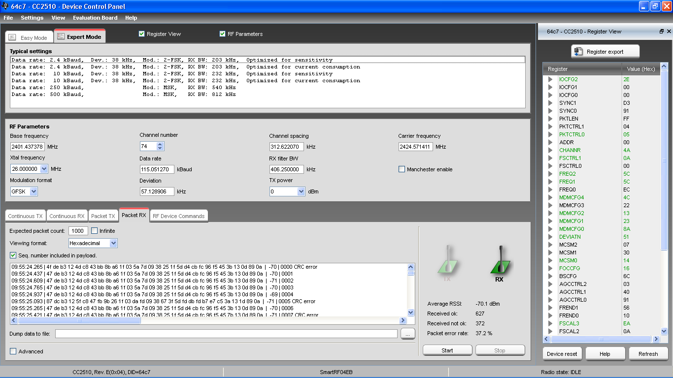
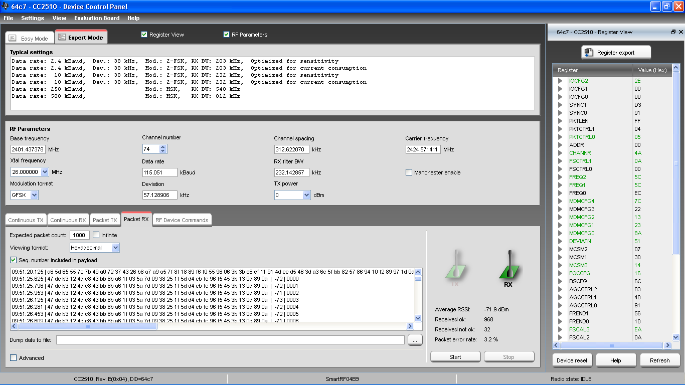
The configuration screenshot is also attached here for your reference.
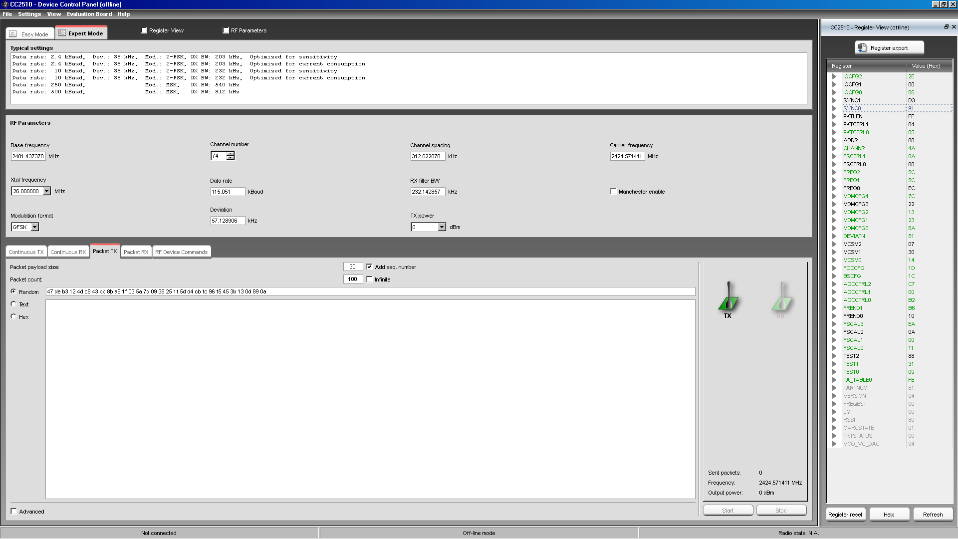 .
.
Then, a RX sensitivity test is conducted using the two SmartRF04EB with the CC2510EM mounted. The test setup is shown below.

The SmartRF Studio 7's Packet TX and Packet RX functions are used to send/receive the packets.
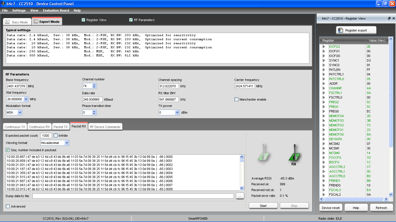
During the test, it shows that the RX sensitivity with this configuration is about - 80 dBm. However, if the default 250 kbps configuration is being used (the one with the MSK modulation supplied by TI), the RX sensitivity performance is much better. Could someone please help to confirm this test result? If confirmed, what is the reason for this difference? And in general, how should I setup the radio correctly? Is there a set of rules that needs to be followed?


