


Hi, I'm using an Olimex development board with CC430 at 38.4k baud, 915MHz. In the CC430 user guide, it says that I must generate a similar table to the one in 25.3.3.6.4.1 with different MAX_DVGA_GAIN and MAX_LNA_GAIN values. I have been setting the AGCCTRL2 registers with different values and reading off the RSSI values when the radio is in RX mode. I got this table
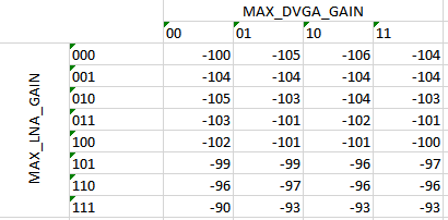
Compared to the pattern of numbers in the user guide, this table is definitely incorrect. Can I please get a pointer on how to get the CS RSSI value correctly? Thanks.
This is my code for thus far. It runs on 1 device that is just sitting there by itself (without any other devices sending data)
#include <msp430.h>

#include "main.h"

#include "../prj40_core/hal.h"
#include "../prj40_core/phy.h"
#include "../prj40_core/RF1A.h"
#include "../prj40_core/RFPacket.h"

#define BYTETOBINARYPATTERN "%d%d %d%d%d %d%d%d"
#define BYTETOBINARY(byte)  \
		(byte & 0x80 ? 1 : 0), \
		(byte & 0x40 ? 1 : 0), \
		(byte & 0x20 ? 1 : 0), \
		(byte & 0x10 ? 1 : 0), \
		(byte & 0x08 ? 1 : 0), \
		(byte & 0x04 ? 1 : 0), \
		(byte & 0x02 ? 1 : 0), \
		(byte & 0x01 ? 1 : 0)

#define	DEVICE_1
#define RSSI_SAMPLES		20

uint8_t RxBuffer[255], RxBufferLength = 0;

int16_t rssiValues[RSSI_SAMPLES];
int16_t rssiAvg = 0;
uint8_t rssiIdx = 0;

uint8_t max_dvga_gain = 0;
uint8_t max_lna_gain = 7;

uint8_t displayedAvg = 0;

uint8_t main(void) {
	WDTCTL = (uint16_t)(WDTPW | WDTHOLD);	/* Stop watch dog timer */

	__disable_interrupt();

	//ACLK = REFO 32768 Hz
	//MCLK = SMCLK = 12 MHz
	//UART 9600
	hal_init430();
	phy_reset();

	phy_enableRX();
	TA1CCTL0 = CCIE;                          		// CCR0 interrupt enabled
	TA1CCR0 = 8191;
	TA1CTL = TASSEL__ACLK + MC__UP + TACLR;         // ACLK, upmode, clear TAR

	WriteSingleReg(AGCCTRL2, (max_dvga_gain << 6) | (max_lna_gain << 3) | 0x03);
	__enable_interrupt();
	while(1);
}

/* Application specific isr */
#pragma vector=TIMER1_A0_VECTOR
__interrupt void TIMER1_A0_ISR(void)
{
	if(rssiIdx != RSSI_SAMPLES) {
		printf("%c", '.');
		rssiValues[rssiIdx] = phy_getRSSI();
		rssiIdx++;
	} else {
		/* done */
		uint8_t i;
		for(i = 0; i < RSSI_SAMPLES; i++) {
			rssiAvg += rssiValues[i];
		}
		rssiAvg = rssiAvg/RSSI_SAMPLES; /* RSSI_SAMPLES samples */

		if(!displayedAvg) {
			P1OUT |= BIT0;
			displayedAvg = 1;
			printf("\r\n");
			printf("MAX_DVGA_GAIN = %d\r\n", max_dvga_gain);
			printf("MAX_LNA_GAIN = %d\r\n", max_lna_gain);
			printf("AGCCTRL2 = "BYTETOBINARYPATTERN, BYTETOBINARY(ReadSingleReg(AGCCTRL2)));
			printf("\r\n%d dBm\r\n", rssiAvg);

			/* setting next setting */
			if(max_lna_gain <= 7) {
				if(max_dvga_gain < 3) {
					max_dvga_gain++;
				} else {
					max_dvga_gain = 0;
					max_lna_gain++;
				}
			}

			if(max_lna_gain == 8) {
				printf("DONE\r\n");
				TA1CTL = MC__STOP;
			}

			WriteSingleReg(AGCCTRL2, (max_dvga_gain << 6) | (max_lna_gain << 3) | 0x03);

			rssiIdx = 0;
			displayedAvg = 0;
		}
	}
}

