This thread has been locked.

If you have a related question, please click the "Ask a related question" button in the top right corner. The newly created question will be automatically linked to this question.

CC2640: GAP_LINK_TERMINATED_EVENT, LL_STATUS_ERROR_CONN_FAILED_TO_BE_ESTABLISHED

Other Parts Discussed in Thread: CC2640

Hi all,

I'm developing with our own PCB for CC2640. Using SimpleBLEPeripheral and TimeApp sample applications I can't connect my Android phone (Nexus 5 with Android 5.1) by bluetooth. Debugging the code I have observed that device advertises correctly and connection is firstly correctly established (GAP_LINK_ESTABLISHED_EVENT received), but inmediately connection ends (GAP_LINK_TERMINATED_EVENT) with reason LL_STATUS_ERROR_CONN_FAILED_TO_BE_ESTABLISHED. 

Trying to solve this issue, I've playing with gaprole parameters: GAPROLE_MIN_CONN_INTERVAL, GAPROLE_MAX_CONN_INTERVAL, GAPROLE_SLAVE_LATENCY, DEFAULT_ENABLE_UPDATE_REQUEST, DEFAULT_DESIRED_CONN_TIMEOUT...., but nothing changed.

By now, I can't get the USB dongle to act as a sniffer and I don't have another mobile phone to test (I am trying to get both of them).

Any ideas or suggestions to unblock this issue will be welcomed.

Thank you.

  • Seeing advertisments but not being able to connect with our default projects -can- indicate that timing is way off.

    This can happen if your external 32.768kHz crystal fails to start up and the LF clock used for the RTC is kept at its reset value (48MHz from HF RCOSC / 1536 = 31.25kHz).

    You can try to set a breakpoint in main() and check the register values of the oscillator module control and status registers.
    They are found in register view at the module DDI_0_OSC and registers CTL0:SCLK_LF_SRC_SEL and STAT0:SCLK_LF_SRC.

    Documentation for these are included with the TI RTOS installer:
    C:/ti/tirtos_simplelink_2_11_01_09/products/cc26xxware_2_20_06_14829/doc/register_descriptions/ANATOP_MMAP/DDI_0_OSC.html

    Edit: If you are able to share your schematic with us we might be able to find potential issues there as well causing this.


    Best regards,
    Svend

  • Hi Svend,
    Thank you very much for your interest and your quick answer.
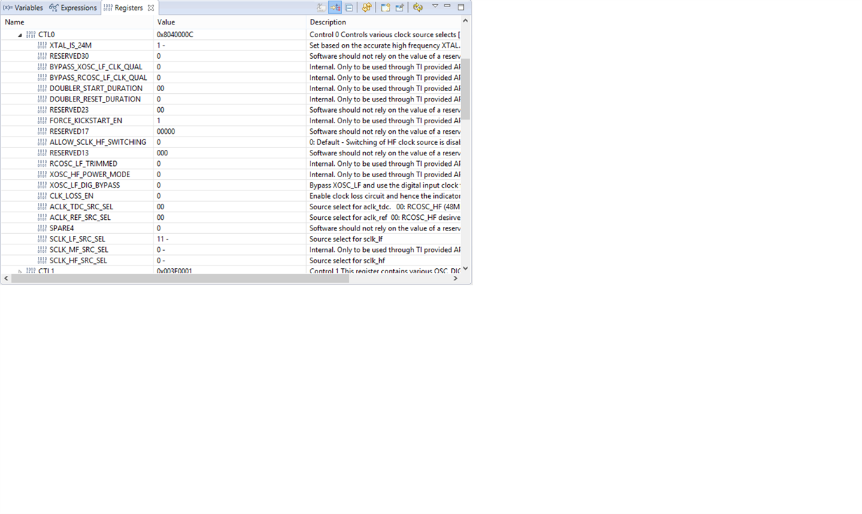
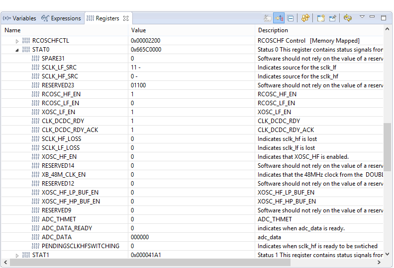
    We've checked the register values you pointed, but the results seem to discard the cause you mentioned, since we found the following:

    •   CTL0:SCLK_LF_SRC_SEL: "11 -" (xosc_lf_clk Low frequency XOSC)
    •   STAT0:SCLK_LF_SRC: "11 -" (xosc_lf)

    Also:

    •   XOSC_LF_DIG_BYPASS: 0

    As shown in following captures:

    Additionally, I share our schematic file. I would be glad if you can take a look to it to see if you find any issue.

    By the way, the references of our crystals are the following:

    • FC-135 32.7680KA-AG (Epson)
    • TSX-3225 24.0000MF15X-AC3 (Epson)

    Exine CC26x0 Development board.pdf

    Thank you very much.

    Regards
    José Antonio Martínez

  • José,

    In that case you might need to tune the 32768Hz crystal frequency offset if the board parasitic capacitance is too large

    Our stack default is configured for a maximum +/- 40 PPM error to save current by needing a small RX time window (since the PPM error is accumulated during sleep between connections).

    The easiest way to fix this is to tune the 32k crystal load capacitors:

    - Output the 32kHz clock to an IO (e.g. DIO8) in main() -after- PIN_init by bypassing the PIN driver and write directly to the registers.

    #include <driverlib/ioc.h>
    #include <driverlib/aon_ioc.h>
    IOCPortConfigureSet( IOID_8, IOC_PORT_AON_CLK32K, IOC_STD_OUTPUT );
    AONIOC32kHzOutputEnable();


    - Measure e.g. 100x 32kHz periods with a high speed logic analyzer sampling at e.g. 100Mhz.

    - Adjust crystal load capacitors to on the board to have the crystal oscillate at the correct frequency. More cap = lower frequency.

    There is also a HCI command to let the stack know which PPM accuracy your crystal has that will adjust the radio time windows accordingly:
    extern hciStatus_t HCI_EXT_SetSCACmd( uint16 scaInPPM );

    Another potential cause can be poor RF performance. It seems you have based your design on the 5XD reference design (differential RF, external bias), is that correct?

    If you have not done any changes to your software our software examples will set up the RF frontend to differential RF with internal bias (CC2650EM_7ID). This might deteriorate RF perfomance.

    To change this you can change the board file search path (see SWRU393 BLE software developers guide ch. 6.2) which will define the correct module for you and make the BLE stack receive the correct RF frontend setting. See also the variable BLE_USER_CFG in main.c and how it is built up using compiler defines.

    Also, the examples enables the LCD screen on our SmartRF06EB so you should remove the compiler symbol TI_DRIVERS_LCD_INCLUDED.

    Regards,
    Svend

  • Hi Svend,

    Unfortunately we don't have a high speed logic analyzer available to use until next week.

    However, we have made some tests, changing crystal load capacitors in the board, with following results:
    * 0pF: failed
    * 8pF: failed
    * 12pF: failed
    * 22pF: failed
    * 33pF: worked, but we need to make some attempts to effectively connect.
    * 47pF: worked (with better success percentage than previous case).

    Moreover, we need to change setting to INTERNAL_BIAS to connect. This is very strange for us, since our board has a EXTERNAL_BIAS solution.

    Also, we have been playing with different values in HCI_EXT_SetSCACmd( uint16 scaInPPM ) (uncommenting line in simpleBLEPeripheral.c and changing the parameter value), but we have observed no changes in behaviour.

    By the way, our design is based on the 5XD reference design (differential RF, external bias), and we had already made the changes you suggested in sample applications, in order to set up the RF frontend and disable LCD drivers (thanks for instructions in any case).

    Today, we are going to prepare some units of the board, but changing to an INTERNAL_BIAS solution to test and compare results. Simultaneously, we are inspecting the code trying to explain the weird observed results.
    Any ideas or suggestions in this way are welcome.

    Thank you very much. Regards
    José Antonio Martínez
  • What is the rated load capacitance of your 32k crystal? The 32.768kHz FC-135 crystal comes in 7/9/12.5pF variants and needing to have more than 33pF on the board to make it work does not make any sense.
    For the 24MHz crystal our example CCFG has 9pF internal capacitance included (the device supports up to 10pF crystals), if you are using a crystal with different load cap then you need to change this in SW(ccfg_appBLE.c).

    Do you have a BLE sniffer available to check whether you see a lot of packets with CRC errors on the air? That could explain the problems with connecting to the device.

    .:Svend
  • Hi Svend,

    Good news, since finally we have found the reason of the failure. However, we have to conced that it was a novice mistake for our part. We added some system_printf() lines to write log messages. We put some of them in functions called to process messages from stack (GAP and GATT messages over all). The delay introduced by this lines themselves was causing the problem. We remove these lines and now all our boards connect perfectly (with the capacitance we already had on our original design and with our original software settings, based on an external bias solution, like the 5XD board).

    I would like to apologize for make you waste your time with this issue, and also express my gratitude for your excelent support and advices.

    Thank you very much.

    Regards.
    José Antonio Martínez
  • Which functions did you add the system_printf() calls to? I may be experiencing similar problems.