I tried the SimpleBLEPeripheral example program in TI BLE1.4.0 stack. I change the P0_7 to P1_5 because I use P1_5 in my board.
1. With POWER_SAVING disable and HCI_EXT_MapPmIoPortCmd( HCI_EXT_PM_IO_PORT_P1, HCI_EXT_PM_IO_PORT_PIN5 ); enable
The VCC is keeping 2.1V. The device can be connected and access normally.
2. With POWER_SAVING enable and HCI_EXT_MapPmIoPortCmd( HCI_EXT_PM_IO_PORT_P1, HCI_EXT_PM_IO_PORT_PIN5 ); disable
The VCC is keeping 3.3V. The device can be connected and access normally.
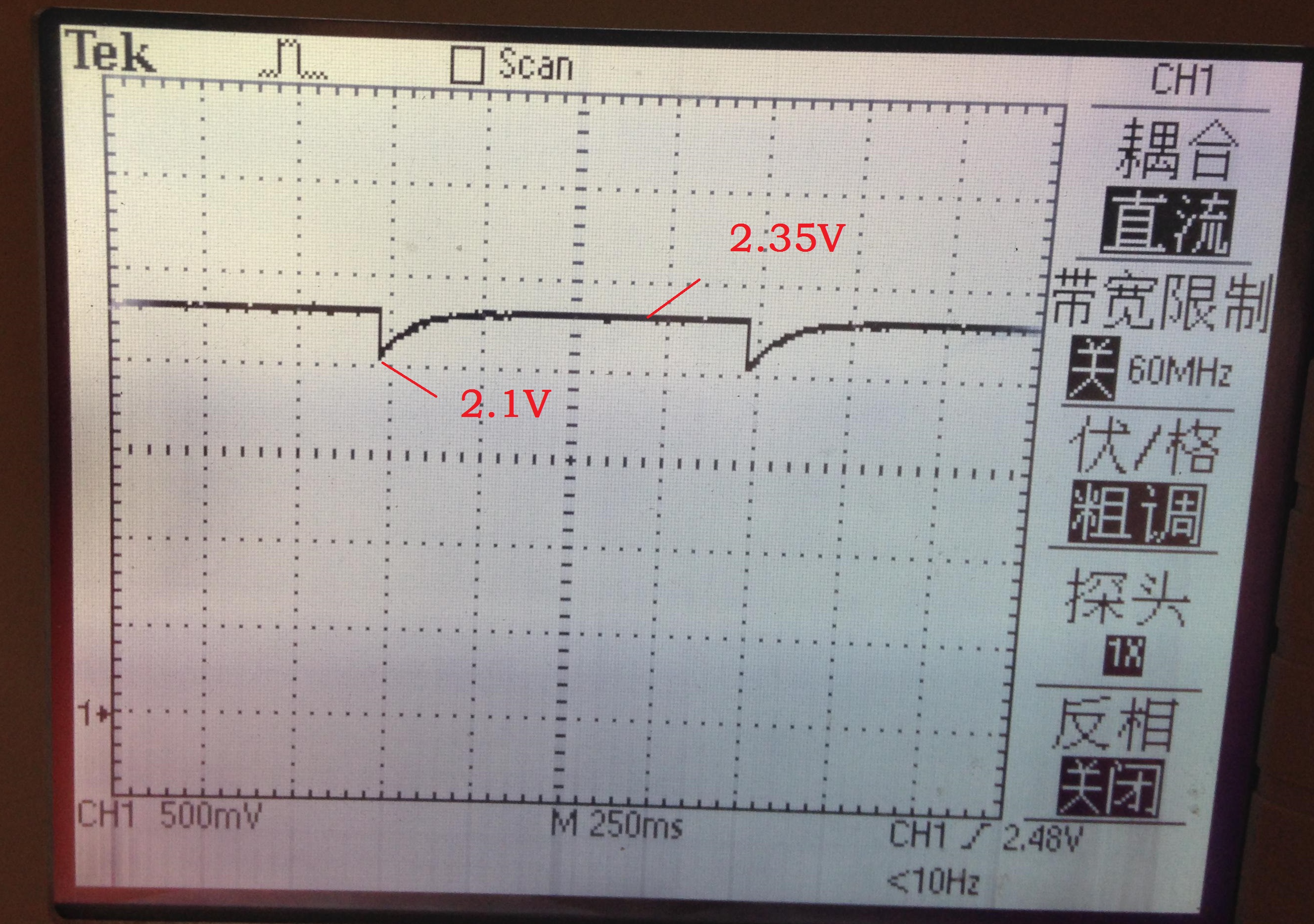
3. With POWER_SAVING and HCI_EXT_MapPmIoPortCmd( HCI_EXT_PM_IO_PORT_P1, HCI_EXT_PM_IO_PORT_PIN5 ); both enable
The lightblue shows "The periperal disconnected while being interrogated" when try to connect.
The waveform of VCC in 3 is shown in the following photo, which I think is allright.
I think it's not a hardware problem, because of the results in 1 and 2. And now I'm using the SimpleBLEPeripheral example program, there should be no problem in software.
I'm confused in this problem. Is there anybody who has succeeded with POWER_SAVING and HCI_EXT_MapPmIoPortCmd( HCI_EXT_PM_IO_PORT_P1, HCI_EXT_PM_IO_PORT_PIN5 ); both enable?
Please help!
Frank