This thread has been locked.

If you have a related question, please click the "Ask a related question" button in the top right corner. The newly created question will be automatically linked to this question.

CC2640 LF clock

Expert 1340 points
Other Parts Discussed in Thread: CC2640

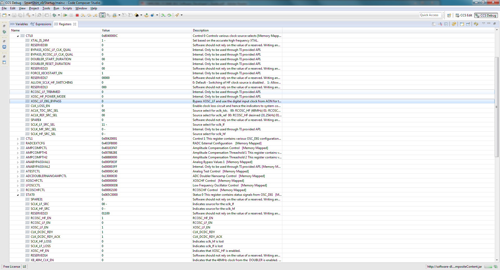
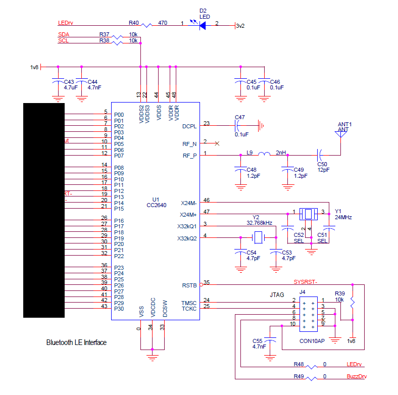
I have a CC2640 and am using a 32.768kHz crystal with 15pf load cap. The crystal shows 32.768kHz on the scope but the output from the CC2640 GPIO is 31.25kHz on the scope. DDI0_OSC.CTL0.SCLK_LF_SCR_SEL = 0x3 (XOSC_LF) and DDI0_OSC.STAT0.SCLK_LF_SRC == 0x0 (XOSC_LF), so the crystal apparently is not being used. However, BLE advertising, connection and notification seem to be working well. I understand the load cap is out of spec. I will try 6-12pF. But will that solve my problem? I need to get 32.768kHz out from the CC2640 in order to drive another IC.

Thanks!

  • Hi Tosa,

    Until the crystal has started up the LF clock will be derived from the HF RCOSC (48MHz) / 1536 = 31.25kHz.
    If you see STAT0.SCLK_LF_SRC not changing from 0 then the amplitude of the crystal is probably too low for the clock to be qualified.

    However it does not make sense that the crystal did not start up and that you are able to stay in a connection at the same time. Since TI RTOS assumes the RTC to tick at 32768Hz all timing would be off by more than 40000ppm, making it impossible to stay in a connection (500ppm is max and stack is by default configured to 40ppm).

    Could you clarify whether you are actually being able to stay in a connection?

    Regards,
    Svend
  • Hi Svend, yes, the Android app is maintaining BLE connection to the CC2640 even though DDI0_OSC.STAT0.SCLK_LF_SRC == 0x0. What is the purpose of the 31.25kHz clock if 32.768kHz is required? My firmware on the CC2650DK is showing DDI0_OSC.STAT0.SCLK_LF_SRC == 0x11, so it's correct. I'm using a different crystal on my board.
  • I tried my board with 6.5pF load cap and am getting same result of DDI0_OSC.STAT0.SCLK_LF_SRC == 0x0 yet BLE works. I'm still getting 31.25kHz clock out. Any ideas why BLE is working and how to get the 32.768kHz clock out?

    Thanks!
  • Hi Tosa,

    The chip needs a LF clock to clock its 32kHz domain (AON). When this is not available from the external clock then it is sourced from the 48MHz RC Oscillator by default.

    How are you outputting the LF clock? You should not be able to connect to the device if the LF clock is 31.25kHz. Are you sure you are connecting to the correct device?

    You need to use a crystal that matches the load you are using. If the load is too high (>12pF) the CC26XX oscillator core might not be able to sustain oscillations as needed.

    Regards,
    Svend
  • Hi Svend,

    Yes, I'm sure I'm connecting to the correct device. The CC2650DK is powered down and only my custom board is powered up and detected by my Android app. I use 

    IOCPortConfigureSet(Board_CLK32K, IOC_PORT_AON_CLK32K, IOC_STD_OUTPUT);	// send 32kKz to GPIO
    AONIOC32kHzOutputEnable();

    to send the clock out. I use the same code on the CC2650DK and get 32.768kHz out along with the correct status, but this isn't the case on my custom board. I'm using Abracon ABS07-32.768kHz-6-T with 6.8pF caps. It's oscillating at 32.768kHz. Any other thoughts?

    Thanks!

  • Did you do any changes to the CCFG section wrt LF clock source (appBLE_ccfg.c) or modify the RTC tick speed?

    Unless doing that I cannot understand how you are able to maintain a connection if the 32k crystal is not used as LF clock source. The only exception would be if you have disabled POWER_SAVING as a compiler symbol in the stack image. In that case the radio would always be on and the radio timer will not need to synchronize with the RTC timer using the LF clock.

    BTW, the ABS07-32.768kHz-6-T description indicates you are using a 12.5pF load crystal. This might fail to oscillate if you have too little/much load capacitance on it. The "6" for tolerance seems to not be mentioned in their data sheet.

    Do you have other boards to test as well in case this is an issue with this specific board?

    Regards,
    Svend
  • Hi svendbt,

    I made no changes to appBLE_ccfg.c, didn't change the tick speed, nor did I disable POWER_SAVING. The crystal I'm using specified 6pF load typical, and it is oscillating @ 32.768kHz (when probed using standard 10Mohm probe). Two boards do the same behavior. I don't have other boards assembled yet. Below is a register screen shot, if that helps:

    I also noticed that the HFRCOSC is used instead of the 24MHz crystal on both the 2650DK and my board. Why is this used instead of the crystal?

    Thanks!

  • Hi TI,

    Some differences between my system and the CC2650DK are:
    1) I'm using 1.8V external supply; no LDO or DCDC regulator
    2) I'm using a single ended antenna
    Would these differences require some different configuration, hence causing this clocking issue?

    Thanks!
  • Tosa,

    #2 will not affect the crystal but will affect RF performance. #1 though -might- affect the system as our example projects always enable the DC/DC (DCDC enable is only SW controlled) which can probably cause noise on the VDDR supply. The VDDR_RF pin is the supply for the oscillators and RF modules.

    Would you be able to share your schematic for review + measure the following voltages:
    - DECOUPL (should be ~1.28V)
    - VDDR+VDDR_RF (should be ~1.67V)

    Also, what is the current draw of the board when the flash is erased? (Preferrably CC26XX only)

    Regards,
    Svend
  • Hi Svend,

    DECOUPL is ~1.28 but VDDR+VDDR_RF are both shorted to VDD which is 1.78V. My schematic is:


    which follows the application circuit: from page 32 of the cc2640 datasheet:

    Since I'm basing my system on the CC2650DK SimplePeripheral example, what should I do to disable the DC/DC regulator?

    Also, I don't understand the purpose of the 24MHz crystal if the internal 24MHZ RC oscillator is being used.

    Thanks for your help! 

  • Hi Tosa,

    Tosa said:

    Since I'm basing my system on the CC2650DK SimplePeripheral example, what should I do to disable the DC/DC regulator?

    This is configured in the CCFG (customer configuration) area and applied during boot. The contents of the included file in appBLE_ccfg.c can be copied into that file and edited.

    The following defines are set by default and needs to be changed to the commented ones:

    #define SET_CCFG_MODE_CONF_DCDC_RECHARGE                0x0        // Use the DC/DC during recharge in powerdown
    // #define SET_CCFG_MODE_CONF_DCDC_RECHARGE             0x1        // Do not use the DC/DC during recharge in powerdown
    
    #define SET_CCFG_MODE_CONF_DCDC_ACTIVE                  0x0        // Use the DC/DC during active mode
    // #define SET_CCFG_MODE_CONF_DCDC_ACTIVE               0x1        // Do not use the DC/DC during active mode

    Tosa said:

    Also, I don't understand the purpose of the 24MHz crystal if the internal 24MHZ RC oscillator is being used.

    The 24MHz crystal is used to generate a high-precision clock to the frequency synthesizer used by the radio to generate a RF output.
    Internally this is doubled to 48MHz and also used as the MCU clock.


    Regards,
    Svend

  • Hi Svend,

    I made those modifications, but still see incorrect LF clock status and 31.25kHz output. Do I need to do anything with:

    //#####################################
    // Alternate DC/DC settings
    //#####################################
    
    #define SET_CCFG_SIZE_AND_DIS_FLAGS_DIS_ALT_DCDC_SETTING 0x0       // Alternate DC/DC setting enabled
    //#define SET_CCFG_SIZE_AND_DIS_FLAGS_DIS_ALT_DCDC_SETTING 0x1     // Alternate DC/DC setting disabled
    
    #define SET_CCFG_MODE_CONF_1_ALT_DCDC_VMIN              0x8        // 2.25V
    
    #define SET_CCFG_MODE_CONF_1_ALT_DCDC_DITHER_EN         0x0        // Disable
    //#define SET_CCFG_MODE_CONF_1_ALT_DCDC_DITHER_EN       0x1        // Enable
    
    #define SET_CCFG_MODE_CONF_1_ALT_DCDC_IPEAK             0x2        // 39mA
    

    Also, I'm still not understanding why the 24MHz crystal is not being used on the evaluation kit. Could you please clarify?

    Thanks!

  • Tosa said:
    Do I need to do anything with:

    No you don't need to do anything with this. This is used by boot code to optimize DC/DC performance. We will clean this file up a bit in a future release and move some of these things to a "Provided by TI, do not edit" section.

    Tosa said:
    Also, I'm still not understanding why the 24MHz crystal is not being used on the evaluation kit.

    I am not sure I understand how this is related to your original request. Are you having two different issues? How are you seeing that the 24MHz is not used?

    You would not be able to get a RF output without it and when running the BLE stack the 24MHz is in fact enabled at all times when the device is not in standby.

    Back to the issues with the LF clock:  When you see SCLK_LF_SEL being XOSC_LF but the source not being the same it is basically because the crystal has not started up for some reason. Would it be possible for you to solder over the crystal + caps used on the evaluation module onto your board?

    It should not be possible to stay in a connection if the 32kHz clock is almost 5% wrong since the device would wake up and try to go into receive way too late so I find it very strange that you are able to do that.

    Regards,
    Svend

  • Hi Svend/TI, any comments to my last post? Thanks!
  • Hi Tosa,

    I am not fully sure which post you refer to.

    Do you have any TI evaluation module (EVM) available? I would try soldering over the 32k crystal + load caps over to the EVM and vice versa to try to find out what the reason might be for the crystal not starting up.

    Regards,
    Svend
  • Oops, sorry I didn't see your 11/3 reply. Apologies for my 11/13 post. Anyhow, I'm still debugging this (in the background since my system still "works") while I work on other aspects of my project...
  • Hi Tosa,

    Svend will be able to explain better to you why the crystal may be needed, however the DC-DC config as well as RF config (single ended) can be found within the CCFG. See ccfg_appBLE.c within the Startup in your IDE. Be sure to read the comments in these files and understand what is affected by changing them.
  • Hi Sean,

    I confirmed that the HF clock does indeed use the crystal; that was just a side question that I had while looking at this LF clock issue. What I noticed is that the HF clock starts off with the RCOSC_HF then switches to the XOSC_HF. My firmware matches the SimpleBLEPeripheral for this.

    I'm still having trouble with the XOSC_LF. I'll try some hardware experiments that Svend suggested and report back. In the meantime could you/Svend please take a look at these screen shots of the DDI0_OSC register? "start" meansthe firmware has just been loaded and paused at main(); "pause" means I ran then paused the firmware. Specifically, the registers BYPASS_XOSC_LF_CLK_QUAL and BYPASS_RCOSC_LF_CLK_QUAL are 1s in SimpleBLEPeripheral but 0s in the newfw. Thanks!

    2211.pix.zip

  • Hello Tosa,

    It seems in you SimpleBLEPeripheral images the LF crystal has started up fine while in the newfw case the LF crystal does not start up.

    The LF_CLK_QUAL bits are used to control the clock qualifiers of the LF clock sources in the CC26XX. There is a bug in these that can cause LF clock glitches when entering standby. When the selected clock source is ready, TI RTOS will disable these qualifiers and will prevent the device from going to standby until this happens.

    Regards,
    Svend
  • Hi Svend,

    Are you saying that my BLE is working since the system is never going to standby? Could you please elaborate on the "bug in these that can cause LF clock glitches when entering standby"? Probing the crystal on the newfw board shows that it's oscillating at 32.768kHz.

    I'll try the using the same crystal as on the CC2650DK on the newfm board. The CC2650DK's BOM shows Epson FC-135 32.7680KA-AG0 for Y1 and 12pF caps for C17/18. I'm having trouble understanding Epson's datasheet to confirm the crystal values, but other vendor web sites shows this should be 7pF. Could you please confirm the crystal and load caps used on the CC2650DK?

    Thanks!

  • Hi Tosa,

    According to the registers in the newfw images the device has not switched over to using the LF XTAL. Why it doesn't switch over to the LF XTAL is still not known to me. Reasons can for example be that the crystal does not oscillate with high enough amplitude or that the added capacitance causes the total crystal load cap to be enough for the crystal to start oscillating.

    Regards,
    Svend
  • Hi Tosa,

    AG0 is CL = 7 pF.

    So the load caps should be approximately 12 pF. (2x 12 pF in series = 6 pF; 6 pF + some parasitic cap ~= 7 pF)

    Cheers,
    Fredrik
  • Hi Svend/Fredrik,

    I got around to swapping the xtal on my board to the Epson, and now it works :) It seems like amplitude was the culprit. Thanks for your help!