This thread has been locked.

If you have a related question, please click the "Ask a related question" button in the top right corner. The newly created question will be automatically linked to this question.

Unable to program external board using JTAG ICDI on CC3200 Launchpad

Other Parts Discussed in Thread: CC3200

Hi,

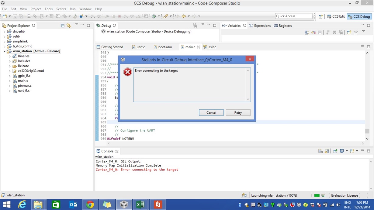
TMS,TCK, TDI, TDO, Vcc & Gnd connections are made from CC3200 launchpad to external(CC3200) board but unable to program the board and getting the below error.

Please let us know how to debug the hardware as the schematics of the external board is a copy of CC3200 launchpad cant able to guess the issue.

  • So you are attempting to use the CC3200 as a programmer/emulator, to program your custom board.

    I have not tried to do this on the CC3200, bit have successfully achieved it with the Tiva C using the following instructions. Perhaps these instructions may assist....you need to be looking as "Debug Out" - http://processors.wiki.ti.com/index.php/Stellaris_LM4F120_LaunchPad_Debug_How_To

    Glenn
  • Can you also connect the RESET output from the Launchpad (pin P2.5) to the target board.

    Also confirm that the target board has the SOP values held at 000.


  • Can you confirm if the CC3200 has booted up correctly. Please check for the following
    1. Voltage on VDD_ANA (pin 48) . It should be 1.8V
    2. Voltage on VDD_DIG (pin 9) . It should be 1.2V.
    If you cannot see these, then the hardware has an issue.
    If this is OK, then check if the 40MHz clock is oscillating..
  • Hi Prajay,

    We made the reset connection and tried but was not successful.

    We measured the voltage i.e. @ VDD_ANA : 1.02V and VDD_DIG: 1.44V, If this is the case what could be the hardware issue as schematics and the component values we used are as per ref schematics, so can you please help us in debugging hardware??

    The SOP settings are 000, also we tried settings for 2-wire programming(100) but status remained same.

    Interesting thing is When we power up the board 2 LED's glow up that are connected to GPIO_10 & GPIO_11.so what it indicates??

  • Hi Folks,

    Any updates??

  • How did you connect the two boards? Separate wires, Flat cable? And how long are they?

    In other words; Do you have a too high crosstalk between the connections due to a too high capacitance?

  • Hi Leo,

    We have made the connection using the wires of 7-8cm's from CC3200 launchpad to proto board.

    The same wires we use to program MSP430 proto boards, so dont see problem with the wires.


  • From looking at your voltages it looks like the hardware is not booting up correctly. Can you connect an oscilloscope at the VDD_ANA pin and send us the snapshot after toggling nRESET from low to high. Also the VDD_DIG should be at 1.1 to 1.2V. Are you sure you are looking at the correct pin?
    Also send us a picture of your setup showing the power supply connections.
  • The wire lengths doesn’t look too long. All wires needs to be same length, including Vcc and GND.

    Vageesh KM said:
    The same wires we use to program MSP430 proto boards, so dont see problem with the wires.

    This is not applicable while you will use for the MSP430 another tool/driver.

    How do you RESET your proto board? Is there any capacitor connected here?

    Additionally to Prajay, check also the JTAG signals including RESET with a scope.

  • Hi Prajay/Leo,

    I am getting the voltages as given in check list, but I am getting "error connecting to Target" while programming so can you please guide me with next steps to debug??

  • If the voltages look fine, then the suspect is the state of the SOP[2:0] pins. it should be 000.
    If that is also fine, then check for TDO/TDI swap.
    Is programming the s-flash over the UART using uni-flash tool working fine? This would imply no major issues.
  • Any update on this problem?