This thread has been locked.

If you have a related question, please click the "Ask a related question" button in the top right corner. The newly created question will be automatically linked to this question.

RF430CL330H Antenna design

Other Parts Discussed in Thread: RF430CL330H, TMP007, PCA9306, TMP103

Hi

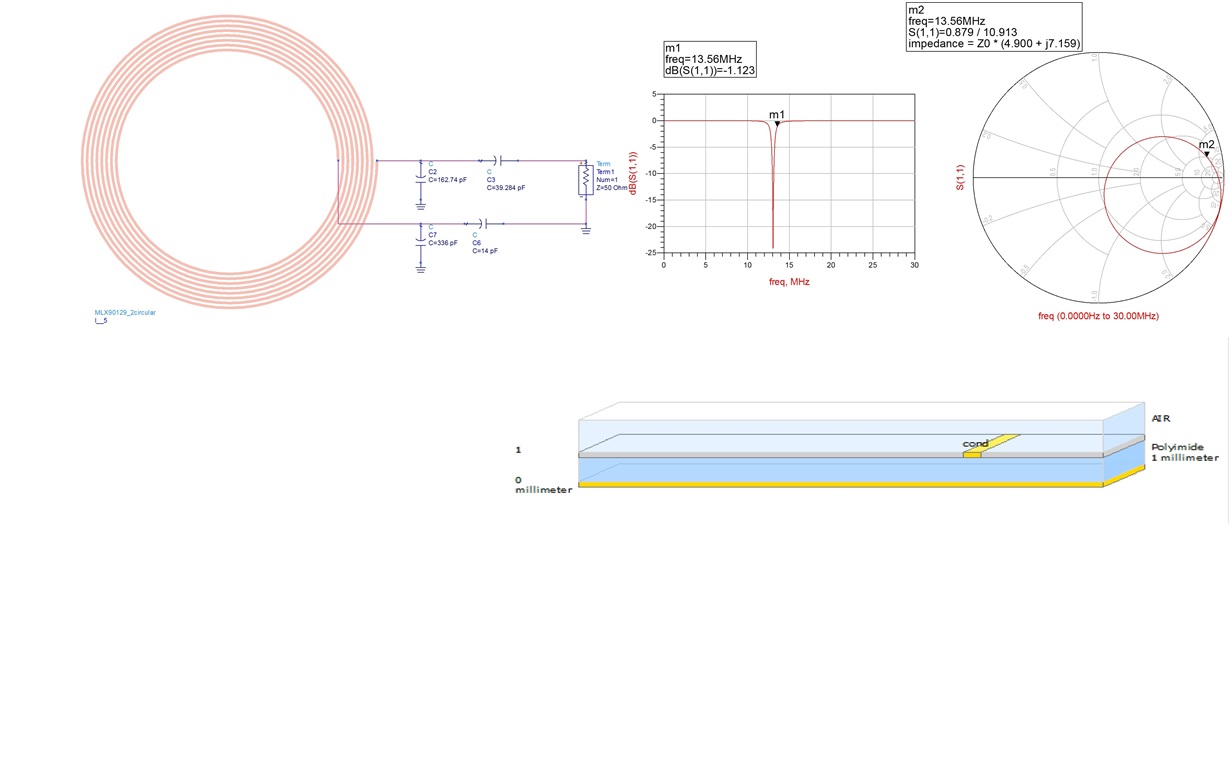
Based on RF430CL330H Antenna design guide ,I designed NFC antenna and I attached simulation result and Substrate which i used. N=8, W=.25mm, S=.2mm and Ro=14mm. After calculation i got inductor value 4.20 micro Henry and Capacitor 32.79 pF. Please i need some comments because i am planing to use this IC for my projec.


Thanks


  • Hello,

    Your inductance is too high.  The RF430CL330H already has internal parallel capacitance of 35pF.  4.2uH with zero external capacitance will already be too low at 13.12MHz.  I recommend to aim in the 2.5 - 3uH range and then tune it to resonance with additional external capacitance.  If you have too high inductance, the only way to fix it is to reduce the inductance value(remove turns, make traces wider, etc).  If the inductance is too low and does not provide resonance at ~13.56MHz using the internal cap, it is easy to fix by adding additional external capacitance.

  • Hi Eddie ,

    Thank you for answer. I want some comments from you ...

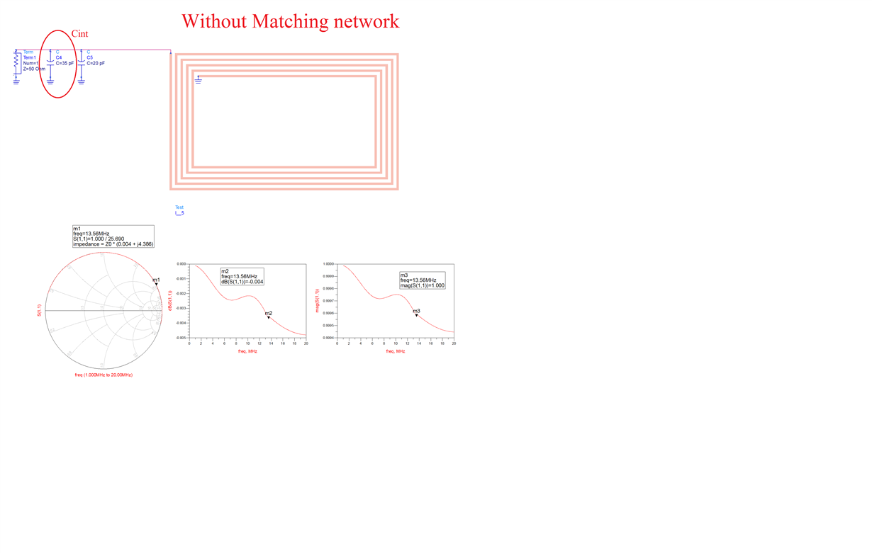
    1. First design which is without matching circuit and and i used external capacitor to fix the inductance value and i got 2.56 micro H as u said your last comments.

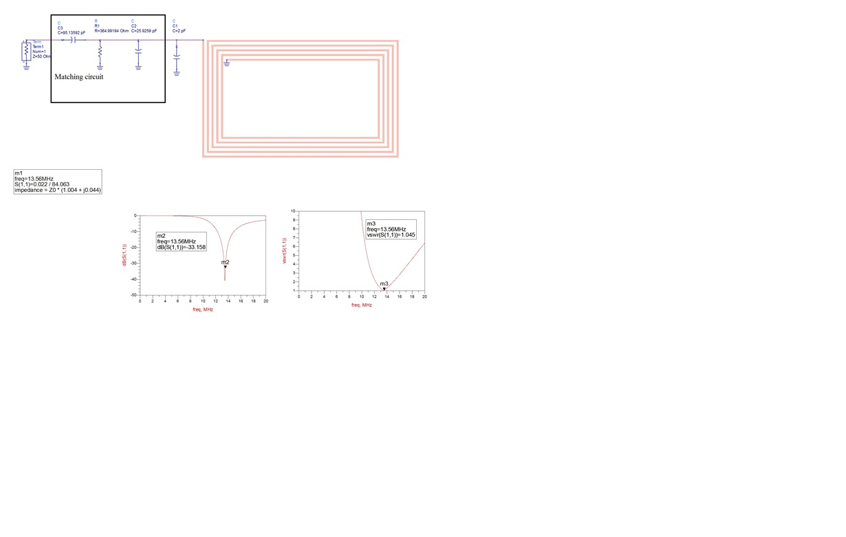
    2. In Second design I used matching circuit and i got very low inductance value but i got S11 and vswr as expected.

    3.How can i get expected inductance value with matching circuit?

    Can you tell me why i got difference value and vswr and matching circuit is really important for this design?

     If the inductance is too low and does not provide resonance at ~13.56MHz using the internal capacitor........can you explain me little bit .....

    How

    I uploaded my design for your comments......


  • The inductance should be measured without any matching components(should be disconnected from chip also).  After the inductance of the coil alone is determined, then use the formula for resonant frequency to determine the required C value.

    If the inductance is too low and does not provide resonance at ~13.56MHz using the internal capacitor........can you explain me little bit .....

    In regards to my statement about inductance too low or high, let me explain.

    If inductance is too high, lets say 4.5uH for example, it is not possible to resonate at 13.56MHz.  The closest you could get would be ~12.68MHz, since we have 35pF internal capacitance.  Formula is 1 / 2pi*sqrt LC.  Adding external capacitance will bring down the resonant frequency, so the only way to tune this to proper resonance is by decreasing the inductance(remove turns and/or make the traces thicker).

    If the inductance is lower, lets say 2uH, then the resonant frequency with the internal 35pF cap is ~19MHz.  We can then decrease the resonant frequency by adding additional capacitance.  Total capacitance of ~68pF will get it to ~13.6MHz.  This would be the 35pF internal + 33pF external in parallel. 

  • HI Eddie,

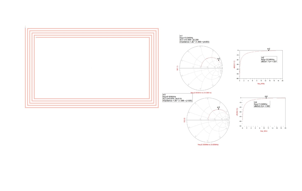
    Thank you very much for your important comments. I think i got your points and your comments will help me to develop my project. Based on your comments i modified my antenna.Plese if you give some comments on my design. It will be very helpfull for me. If you look my design (rectangular antenna ) i got inductance value 2.73 micro henry at 13.56 MHz frequency and for circular antenna  i got 1.58 micro henry. So consider 35 pF  internal capacitor i nedd to add a 15 pF external capacitor in parallel(rectangular antenna) and 52 pF in parallel for circular antenna to get resonance.

    1. Do you think my calculation and design  is correct?

    2. What you think about my design and Can i procced with those design?

    3.Do i nedd to design any matching circuit for this antenna? i wanna use this design for RF430CL330H ic

    4. How can i reduce antenna size?

    Thank you again for your important comments.


  • 1. Do you think my calculation and design  is correct?  I cannot confirm your calculation .  I would need to know the dimensions of the coil and the trace width.

    2. What you think about my design and Can i procced with those design?  If your inductance calculation is correct, these designs are good.  It is also suggested to verify your calculation by measuring the inductance of the actual PCB or wirewound coils at 13.56MHz using network analyzer.  The calculations will get it close enough to be funtional, but you can optimize the antenna if you can measure at 13.56MHz. 

     3.Do i nedd to design any matching circuit for this antenna? i wanna use this design for RF430CL330H ic  There is no need for an impedance matching network.  You simply need the parallel capacitor to create the resonant tank circuit.

    4. How can i reduce antenna size?  If the antenna size is reduced, you will need to increase the number of turns and/or reduce the trace thickness to bring the inductance back into a tuneable range.  Of course, the smaller the antenna, the shorter your read range, so I always recommend using the largest coil that your application can tolerate.

  • Hi Eddie,

    Thank you for answer.

    1. For rectangular loop antenna N=5, L1=50,L2=30,W=.3 and S=.53

    2. For circular loop antenna N=8,R0(Outer Radius)=21,W=.52 and S=.25

    All unit are mm.

    3. RF430CL330H IC have two pin Ant1 and Ant2. How can i use those pin? From data sheet I think Ant2 pin will attach with Antenna ground pin or I need to design two antenna?

    4.How can i calculate Power through CAD software?

    In my project i will use TMP007 ic and ​PCA9306(voltage doubler) ic.TMP007 need minimum 2.2 to 5.5 V and my plan is i will use field power (no battery ).

    Thank you for support

  • Your calculations look good, but I want to make sure I am interpreting it correctly.  Please let me know if below is correct.

    N = number of turns

    L1 = Length of rectangle

    L2 = Width of rectangle

    W = spacing between traces?

    S = trace width


    You do not want to ground one end of the antenna.  This is simply a resonant tank circuit. 

    I am not sure your best method to calculate power through software.  I beleive Ansoft offers some simulation software for this, but we do not use it here.

    I recommend doing something similar to what I have done on the TI Design below with the schottky diodes on the antenna.  The internal limiter on the RF430CL330H will keep the recrified voltage at ~2.6V, so you probably dont need the doubler.  This design uses TMP103 and field power.  If you are interested, I can send you a board to check out.  Send me a private message and I can get your mailing info. 

    http://www.ti.com/tool/TIDA-00217?keyMatch=tida-00217&tisearch=Search-EN-Everything 

  • Hi Eddie LaCost ,

    I tried to send you private message but unfortunately i did not find your name. My email address is liunahid1@gmail.com

    Thanks for your help
  • Hi Eddie,

    I sent you email with my address. What you think which software i can use for simulation.

    Thanks
  • Great, I'll get a couple boards to you. 

    Ansoft is the only simulation software I have heard about and used minimally myself.  Generally, simulation is not required and we can use observed read ranges from previous boards with similar antenna form factors to estimate the read range.  What type of reader will be used for your application?  Antenna size and output power would be useful information or if you are using a phone, I can help estimate the expected range. 

  • HI Eddie,

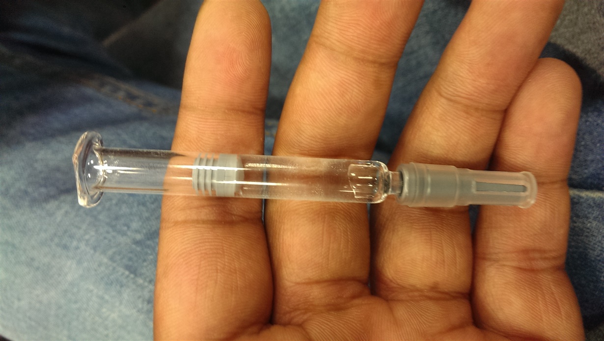
    I sent you an email with my project description. Please check your email. We wanna measure drug which shown in picture


    Sincerely,

    MD NAHIDUR RAHAMAN


  • HI Eddie,

    I send you a email with schematic. Kindly can you review my schematic. How can i debug firmware .

    Thanks,