This thread has been locked.

If you have a related question, please click the "Ask a related question" button in the top right corner. The newly created question will be automatically linked to this question.

rf430frl152h programming circuit

Other Parts Discussed in Thread: RF430FRL152H, RF430FRL152HEVM

Hi there,

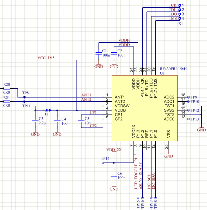
I have a hardware problem in figuring out how to program an RF430FRL152H low voltage device. I just want to implement my own design but unfortunately I forgot to include the levelshifters between the programming interface and the chip (TDI, TDO, TCK, TMS, RST).

First question: Is there an msp-programmer (I have the MSP-FET430UIF) that can be connected directly to the JTAG interface or do I need to include these levelshifters in my designe (or on a middle board).

Anyway, to solve that problem I used an RF430FRL152HEVM-board, disconnected that chip and connected these pins (TDI,..., RST) with wires to my own board.

So far it's supposted to work (haha, it always supposed to work) anyway. CCS6 pops up following message:
"Error connecting to the target: Security Fuse has been blown"

Well I'm sure I didn't or how would that be possible if I doesn't explicitly write that in my code?! By the way the code which I wanted to download has been downloaded on the eval-board before, so it shouldn't malfunction on an equivalent chip.

Second question: Whats the minimum hardware (which C's are "must have") to get a program downloaded on a RF430FRL152H without having an eval-board?

Huu, you will be a biiig help for me!

Best regards, nik

  • You do need a middle board.  You could explore this MSP-FET430UIF + MSP-FET430U092 combo.  However, I would recommend repurposing a RF430FRL152HEVM for this.

    The key connection that you could be missing is powering the target RF430FRL15xH not by VDDB but rather by VDDSW (pin 3).  The other connections are rather straightforward.  So on the EVM SV7 can be used as a 1.5V power supply (power is coming from the 1.5V LDO to VDDB here however).

    If you continue to have problems programming the target device by the EVM I could help you with that if you go into more detail on the connections that you are making.

  • Thank you for responding.

    VDDB and VDDSW are connected together. Well, below (Figure 1) you can find my schematics. What I forgot was is to connect the RST, but i put a wire there, so that should be solved. Figure 2 and 3 show the modifications on the EVM board (schematics found in "RF430FRL152HEVM User Guide").

    So I soldered wires to these points and connected them to my board. Eventually it looks like shown in Figure 4. Please let me know if I have to provide more informations.

    best regards, nik 

    Figure 1: RF430FRL152H - Costum design

    Figure 2: Modifications on the RF430FRL152HEVM board, part 1/2

    Figure 3: Modifications on the RF430FRL152HEVM board, part 2/2

    Figure 4: Result of the modifications

  • OK, it seems to work now. But if you want to know what I changed, well: I actually changed the supply from (before) an external 1.5 V supply to the 1.5 V supply from the EVM-board. Not that this made it work, but it makes sence, lets say "one improvement". Then continued to measure the signals but it still didn't work. Unpluged and pluged each connector by it self many times to look at the signals,... running out of ideas,... just tried it again. And yes it worked... *wuusaaa*, its not easy!! Thank you any way for your help!!