This thread has been locked.

If you have a related question, please click the "Ask a related question" button in the top right corner. The newly created question will be automatically linked to this question.

TRF7970A / DLP-7970ABP use case maximum range

Guru 18595 points
Other Parts Discussed in Thread: TRF7970A, DLP-7970ABP

Good morning,

I have read several E2E threads about this. Thanks for answering them, my questions will be built considering the others.

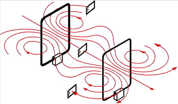
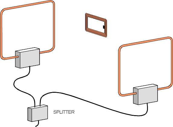
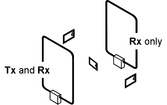
I plan to use 7970A as a reader for vicinity (15693, NFC-V, whatever you call them) tags. I was wondering if it is possible to detect a pedestrian going through a door, carrying a card-sized tag, for example in his / her pocket. Thus, range should be 1 meter or so. I was thinking in placing an antenna around the door, or placing it sideways outside the door in an information panel, even if people probably would not stare at it, it is just a camouflage (just imagine this next to the door). So yes, reader antennas could be quite large.

In other posts, TI staff recommends stuff from "FEIG Electronic" for purposes like this, but I'm not sure if they refer to "high power readers" or "antennas". Since I would prefer to stay with DLP-7970ABP / TRF7970A it is important for me to clarify this since I do not know if the TI reader outputting 200 mW with a big antenna would be enough for my purposes. In fact, I do not even know if the TI reader can support such big antennas. Yes, I know I should perform antenna matching with VNA if the reader can support them.

Please, let me know your opinions. BTW, I know there are other technologies for similar purposes, it is just a matter of determining the suitability or not of my schema. Have a really nice day!

  • The TRF79xxA family of NFC/RFID transceivers put out maximum of 200mW of power. It would have to be connected to an amplifier and multiple antennas to provide a substantial field for the application distance requirement you requested of 1 meter. Because of the power, there is a limit to how big the antenna can be, because eventually there will be a hole in the middle that will not contain enough flux density to power the tag(s). So about 300mm x 300mm is a reliable size for this kind of power and with a badge (if punch-able type) will read out consistently with a range of about 20 to 20cm. if a full ISO ID1 format tag, then about 28cm. 

    so you need larger antennas on the reader side to go along with the higher power needed for the size of what they need to be. 

    Further, in this application, since the badges are small relative to the coils needed to reach out this far - (this is the Vicinity part of the technology) - in many cases, you will see that gate antennas (or pairs) are arranged such that there is enough density in the area where the tag will pass and oriented and phased correctly so as to induce the maximum amount of current from one side to the other, while still accommodating possible variations in orientation of the transponder itself as it passes through the field.

    the images below illustrate simply two of the popular arrangements, with transponder orientation considerations. 

    in phase - this is used when tag orientation is known and controlled

    out of phase (here using a splitter, also possible using complementary or multiplexed antennas, as well as adding delay(s) with coax cables)

    these are the tag orientations generally seen in the access control gate application.