This thread has been locked.

If you have a related question, please click the "Ask a related question" button in the top right corner. The newly created question will be automatically linked to this question.

TRF7960: Read Single Block issue

Part Number: TRF7960
Other Parts Discussed in Thread: , DLP-7970ABP

Hi,

we recently found a problem in Read Single Block we never seen before.
It seems it happens after we slightly modify our RFID board simply integrating a impedance in the board circuit instead of connect it externally.

The problem is that in rare cases the Read Single Block command returns a wrong value in the last byte of the block.
The wrong value is always the same if the data in the block remains the same but it changes if data change.

The datalogger shows that everything is correct in the SPI data exchange, it is always the same (same data, same timing) when the value is correct or incorrect and it is compatible with TI examples.
This is the correct sequence that happens almost every time (all bytes of the block are correctly 0x02):

This is the wrong sequence (all values and timings are the same, even the ones not shown in the picture) but the last byte is not 0x02 but 0x1B

Anyone have an idea of the cause of problem?

Our dubt is: do we need to implement the workaround 4 described in SLOA155 "Wrong Data Due to Overshoots"?
It refers to ISO14443A decoder but we use ISO15693. If so can you explain better how to implement it?
We thing we are using a TRF7960 instead of TRF7960A (we are checking with the designer of our board). How can we distinguish them? Could we try to update the chip to TRF7960A?

Thank you in advance.

Best regards

Alessandro

  • Hello Alessandro,

    Alessandro Marozin said:

    It seems it happens after we slightly modify our RFID board simply integrating a impedance in the board circuit instead of connect it externally.

    Can you explain more details about this? What do you mean by integrating an impedance on the board? Can you describe the details of the change?

    Given that is what changed to cause this issue, that is the first place that we should focus on looking.

    That said a couple other questions:

    1) What is your SPI clock rate

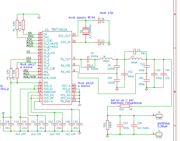
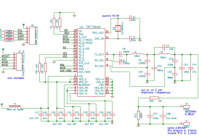
    2) Can you share the schematic for the TRF7960 portion of your circuit

    3) Also you say the error is rare, do you have a rough idea on the occurrence rate?

    Regarding the workaround for Wrong Data Due to Overshoots, that issue has never occurred for ISO15693 as far as I am aware, so I don't believe you need to address that workaround.

    For distinguishing 60 vs 60A, the only real way is to read the markings on the IC.

    Updating to a 60A would not be a bad idea as it is a newer device than the 60, but I am doubtful it would immediately solve your issue either. The only times updating from 60 to 60A has provided improved performance is when using ISO14443A.

  • Thank you for the quick reply.

    We changed a filter in the input 5V. We use an impedance to reduce noise. In the first version the impedance was external to the circuit and now it is integrated.
    But I do not expect this can change something in the communication (the error seems is not be generated by noise). Do you agree?

    1) We set SPI clock rate as follow:

    SPCR = 0b01010000;

    So bits 0 and 1 is both 0. This means frequency is FCK/4.

    FCK is 8Mhz so SPI clock rate is 2Mhz (this is confirmed looking to data logger)

    2) Here is the schematic

    3) Our acceptance test sends N times a sequence of 20 "Read Single Block" on 4 different tags. We have about 1 error every 10 to 20 sequences (so from 5% to 10%)... but not on all boards (some boards never gives the error).

    Best regards

    Alessandro

  • Any suggestion? Thank you.
  • Hello Alessandro,

    Sorry for the delay in replying.

    Looking at the schematic, it looks like you have VIN tied to I/O_1 and I/O_2. You also commented about 5V so it sounds to be like you are sourcing VIN with 5V?

    If so, that would be a large issue as I/O_1 and I/O_2 max voltages are limited by VDD_IO which would be far less than VIN.

    Can you clarify that portion of the schematic?

    Another note is that MOD and ASK/OOK don't have 1k pulldowns on them. You can use the internal pulldowns in a capable MCU if possible, but otherwise you need external pulldowns for those pins.

    I do agree that the change in the 5V input for noise filtering shouldn't affect you in normal circumstances, but now that the VIN line seems to be tied to I/O ports, I could see that being an issue.
  • Hi Ralph,

    I checked with electronic designer. I/O_1 and I/O_2 are already connected to VDD_X... the schematic I sent you was not updated, sorry. Following is the updated one.

    MOD and ASK/OOK was NOT connected. Is it correct? Do I need to connect to the ground.

    As a workaround do you think there is a way to detect bad data?

    Thank you.

    Best regards

    Alessandro

  • Just to be sure about the software, when I switch on the TRF I make the following setting in the registers:

    _delay_us(400);

    SPI_TrfWriteRegister(TRF_ADDR_REGULATOR_CONTROL, 0x87); //TRF_ADDR_REGULATOR_CONTROL = 0x0B
    SPI_TrfWriteRegister(TRF_ADDR_CHIP_STATE_CONTROL, 0x21); //TRF_ADDR_CHIP_STATE_CONTROL = 0x00
    SPI_TrfWriteRegister(TRF_ADDR_ISO_CONTROL, 0x02); //TRF_ADDR_ISO_CONTROL = 0x01
    SPI_TrfWriteRegister(TRF_ADDR_TX_PULSE_LENGTH_CONTROL, 0x80); //TRF_ADDR_TX_PULSE_LENGTH_CONTROL = 0x06
    SPI_TrfWriteRegister(TRF_ADDR_MODULATOR_CONTROL, 0x21); //TRF_ADDR_MODULATOR_CONTROL = 0x09
    SPI_TrfWriteRegister(TRF_ADDR_RX_NO_RESPONSE_WAIT_TIME, 0x14); //TRF_ADDR_RX_NO_RESPONSE_WAIT_TIME = 0x07

    _delay_ms(23);


    Do you think I need to use RSSI register to read input signal level and eventually switch channel?
    But, if the problem is signal strength, I do not expect a systematic error like the one I am seeing.

    Thanks
    Alessandro
  • Hello Alessandro,

    MOD and ASK/OOK should be pulled to ground with 1k pulldown either on the board or at very least by MCU internal GPIO pulldowns.

    Have you been able to replicate the issue on multiple boards with the correct schematic for I/O_1 and I/O_2 connections?

    Register setting wise, I don't believe you need to write to the TX Pulse Length Control register as that should be set correctly by the device, but you do need to add in writing to the RX Wait Time register (0x08) and program it with a value of 0x1F.

    Beyond that, the other register settings seem fine.

    The error isn't going to be related to the ISO14443A overshoot, that never affected ISO15693 and the device has been used for many ISO15693 applications without error.

    This could come down to a software issue, are you writing your own firmware from scratch or adapting a TI example?
  • Hello Ralph,

    About MOD and ASK/OOK...  I will ask to our electronic designer to check this. Do you think this can be a possible source of problems?

    All the boards have the correct schematic for I/O_1 and I/O_2, it was just an error in the documentation.
    I can replicate the problem in most, but not all, boards. Moreover, the old boards without the modification in the 5V input filter worked always fine.

    I will try to change the registry settings as you suggested.

    To write my software I adapt a TI example and I compared my data logger samples with TI samples. I think we can exclude a software problem because the data logger reports exactly the same signals with the same timing when the result is correct and when the result is incorrect (and both are compatible with TI samples). The only difference is the last byte of the block that sometimes have a wrong value (as I said the wrong byte has always the same value if value written in that byte do not change)

    Thanks

    Alessandro

  • Hello Alessandro,

    I wouldn't say it is a highly likely source, but that is a deviation from our reference designs so it is a possibility.

    I still wonder what could have changed from the boards with either the filter or other changes. If it worked fine before, something with the hardware change must be causing the problem.

    If it's a new board spin, I wonder if there were any component differences in terms of values or tolerances for the antenna or the 50-ohm match network...? Just spit balling ideas.

    The issue you are seeing isn't something we've really experienced before, so it's a very hard to gauge exactly what is causing it. I don't have a past occurrence to lean back on say 'well this could have happened, try this fix.' Given that it seems to be due to this new board design, that's somewhere to start looking IMO...
  • Hello Ralph,

    we tried to pull to ground (with 1k pulldown) MOD and ASK/OOK with no results.
    we also tried setting RX Wait Time (registry 0x08) to 0x1F, that is the default as far I know. Also nothing changed.

    The interesting thing is that I tried to set RX Wait Time to some extreme values.
    For example with the value 0x01 we NEVER see the problem on Read Single Block but Inventory with multiple tags always fails.

    May be this is the key? Can you tell me the exact meaning of this register and suggest how to find the correct value?

    Also, before Inventory I set every time Modulator Control and No Response Wait Time registries. Do I need to set again also Rx Wait Time Registry?

    Thanks

    Alessandro

  • Hello Alessandro,

    The RX Wait Time is the amount of time after the chips issues the TX EOF that the internal RX decoders are turned off and the device no longer sees an RF response until another TX occurs. That value should never be changed within the RF communication sequence for a single protocol. It only should be altered when starting a new sequence with a different protocol, like switching from ISO15693 to ISO14443A. As far as correct values go, the datasheet lists the recommended values which should be used. The values you mention using as tests are surprising that they even work at all, as they really shouldn't, but in any event they shouldn't be used over the recommendations provided in the datasheet.

    Before each new communication cycle (i.e. starting with Inventory) you should do a soft reset of the device with 0x03 (SOFT_INIT) and 0x00 (IDLE) direct commands (sending them would be 0x83, 0x80 as B7 is toggled to indicate Direct Command) and then followup by re-configuring all the needed registers. This ensures for each communication cycle, the device is starting from a known clean state. So if you have a process that consists of, Inventory, Get System Info, Read blocks 0-20, Write blocks 0-10, and then repeat, after the Write blocks are done and before the next cycle starting with Inventory begins, send out the 0x83 0x80 commands and then re-configure the registers.

    Now that you bring that up, I wonder if applying the SOFT_INIT and IDLE sequence to soft reset the device before each communication round would help resolve your issue... it has had positive effects for many others. Please give that a try.
  • Hello Ralph,

    As you suggested I tried to add commands 0x83 and 0x80 before Inventory but nothing changed.
    Following is the exact sequence I use. 

     _delay_us(400);
     
     SPI_TrfDirectCommand(0x83, TRUE); // SOFT_INIT
     SPI_TrfDirectCommand(0x80, TRUE); // IDLE
     
     _delay_ms(5);
     
     SPI_TrfWriteRegister(TRF_ADDR_REGULATOR_CONTROL, 0x87);   
     SPI_TrfWriteRegister(TRF_ADDR_CHIP_STATE_CONTROL, 0x21);  
     SPI_TrfWriteRegister(TRF_ADDR_ISO_CONTROL, 0x02);   
     SPI_TrfWriteRegister(TRF_ADDR_TX_PULSE_LENGTH_CONTROL, 0x80); 
     SPI_TrfWriteRegister(TRF_ADDR_MODULATOR_CONTROL, 0x21);   /
     SPI_TrfWriteRegister(TRF_ADDR_RX_NO_RESPONSE_WAIT_TIME, 0x14);
     SPI_TrfWriteRegister(TRF_ADDR_RX_WAIT_TIME, 0x1F);    

    I will eventually see your answer in January. 
    Thank you again and Merry Christmas

    Alessandro.

  • Hello Alessandro,

    At this point given what is presented I don't have a clear theory on what could be occurring, especially given that this symptom supposedly only arises when the filter on your 5V line is moved onto the PCB.

    As far as any software concerns go, I would need to see full logic captures of the SPI lines+IRQ at this point to be able to offer any other comments. If you want to try and provide that, then I would recommend getting a Logic State Analyzer from Saleae, as they can log long periods of SPI comms and decode the packets as well.
  • Hello Ralph,

    First of all happy new year.

    Please, find at the link below a capture from Saleae Logic State Analyzer (it expires in 7 days)

    https://we.tl/3HCtWaWsIB

    We use a tag containing the same value (0x4A) in all bytes. We made 5 (addressed) Read Single Block in 5 consecutive addresses (00 to 04).
    4 reads give the correct result but the last gives a wrong result (the last byte contains 0x2A instead of 0x4A (see it at time 0s 58ms 570us).

    As I wrote in my previous post the problem can happen with different tags, in different addresses and with different frequency.
    If the byte contains a value X, when I get the wrong result I will get always the value Y. I mean, if like in this case the byte contains 0x2A then wen I get the error I will read always 0x4A (for different values I will get different wrong values)

    As you can see the Read Single Block sequence is identical (also time intervals are comparable) when I get the correct result and when I get the wrong result.
    In this capture I did not set RX_WAIT_TIME registry as you suggested but I try it and it gives the same result.

    Thank you again.

    Best regards

    Alessandro

  • Hello Alessandro,

    I cannot download that file as our IT firewall doesn't allow for that site to be used.

    You can upload the file directly onto E2E by using the "Insert Code, Attach Files and more..." option to open up the full editor, and then attach the file there (look for the usual paper clip symbol).
  • I tried but the page gave me an error because the file has not a known extension.
    Is it ok now? I attached the file as a web URL.

  • Hello Alessandro,

    I didn't think that it'd have an issue with that, but if so just put it in .zip file? The web link won't work for me, it's the URL of the site that is blacklisted so any form of link doesn't work.

    Edit:

    I tried and had no issue uploading a .logicdata file onto E2E. Outside chance it's because I am an employee, but I doubt they'd differentiate that.

    Anyways, try with a .zip file if it gives you issues again.

  • Hello Alessandro,

    Reviewing your logic capture, it looks like the extra clocking after the Direct Commands is not handled correctly.

    If using an additional SCLK cycle, it needs to be entirely done before SS goes high, which is not the case. Also I am not sure one way or the other as we never tested it but you may need to have the SCLK cycle be comparable to the usual SCLK frequency.

    You may want to try doing the second advise given which is to send a dummy TX byte instead. That is what we do in our software examples typically as it is the easiest.

    You can read the details of this in Section 1.3 of: http://www.ti.com/lit/an/sloa140a/sloa140a.pdf

    I believe this could be the source of your problem as if the Reset FIFO isn't being processed by the TRF7960, then getting corrupted data could occur. Please address this first and see if the behavior improves.

  • Hi,

    I tried with both dummy write and additional clock cycle implemented as you suggested but I still have the sporadic Read Single Block error.
    Moreover with this implementation Inventory does not work at all. TRF responds with IRQ 0x80 (Tx completed) and then 0x01 (No response).

    I will send SPI grabs tomorrow when my colleague that did the tests will send them to me.

    Just a note... I arrived to my current implementation 2 years ago (included additional clock cycle implemented as my previous email) after long discussions in this forum. 
    It worked always well until we modified our board... but I understand that may be the change could get out some previous hardware or software weakness.
    Anyway from a software point of view I have several SPI samples from Texax Instruments (files coming from Saleae Logic Analyzer) and all that samples have the additional clock cycle identical to mine (all other command sequences are also equal). 
    So at this point I am a little bit confused about the correct implementation. 
    I understood that it is better to refer to TI grab samples because documentation was often not correct or incomplete (at least at that time).

    Thank you.

    Best regards

    Alessandro

  • Hello Alessandro,

    From a sequence perspective everything else seems fine. The read of 0x1E at the end isn't something we usually do, but that wouldn't possibly affect this issue. Everything else to me looks fine from what I can tell.

    Usually, in my experiences, a hardware change outside of antenna tuning or power topology changes wouldn't expose any software flaw.

    As far as software goes, if you had SPI samples, those are probably good references though I'll note that in late 2016 there was an up-to-date TRF7960A firmware example provided which would also apply for the 60, so you may want to look at that. The firmware can be downloaded from: www.ti.com/.../sloc297

    I do wonder about one register configuration point... I don't think it should have any effect, but I do recall that register 0x08 for RX Wait Time doesn't always take on the right default values for a given ISO technology. For ISO15693, that value should be 0x1F. I'd add that in to your list of register writes. I'd be floored if that fixed the issue, but it'd be good to have in general.

    I'll review the next batch of SPI captures when they arrive.
  • Hello Ralph,

    as discussed, here are the SPI captures using dummy writes instead of clock inversions.
    There are initial registry settings and 20 Read Single Block. The wrong byte read (0x2A instead of 0x4A) is at time 0s 137ms 900us.

    Best regards

    Alessandro

    dummy_write_error(0x2A insteadof 0x4A)_0s137ms900us.zip

  • Hello Alessandro,

    Looking through the captures, the only other idea that comes to mind for me software wise is to start the device of with the SOFT_INIT (0x03) and IDLE (0x00) direct commands and then a 1ms delay. That is something we recommend as a standard practice to ensure the device starts in a proper state before register configurations etc. - and it is also recommended to be done after encountering errors in communication.

    Aside from adding that in, I don't really see anything else software wise which concerns me.

    Only other thing I can even think of testing would be to see if increasing the SPI clock up to 4MHz would help at all? I don't expect it to as the scope seems to report the 2MHz being reliably output, but I don't really have any better ideas at this point.
  • Hi Ralph,

    I made a test sending soft init and idle commands to TRF at startup but nothing changed.
    To test SPI at 4Mhz I should increase also the CPU frequency to 16Mhz so I need an external oscillator... it is not immediate.
    I test SPI at 500Khz but I have the same problem.

    I also check the hardware in depth with our electronic designer but we found nothing.

    My final thought is that it can be a problem of one or more lots of TRF7960. What do you think about?

    Best regards

    Alessandro

  • Hello Alessandro,

    SPI lower than 2MHz can cause issues as well, so that's no surprise. Understood that higher than 2MHz isn't easy for now.

    I can't imagine this to be an issue with a whole lot of TRF7960's. Such issues ultimately end up being traced back to an application specific element whether it is hardware or software (with the very rare ESD event also a past culprit). But in any event, the easiest way to test for such an issue is to get a TI EVM like our DLP-7970ABP, replace the chip with the TRF7960, and then run TI example software like sloc297 on it.