This thread has been locked.

If you have a related question, please click the "Ask a related question" button in the top right corner. The newly created question will be automatically linked to this question.

RF430CL330H: Chip appears to startup up wrong protocol mode

Part Number: RF430CL330H
Other Parts Discussed in Thread: DLP-RF430BP

My board design has CS = 1 (Hi = 3.3V) on start up, but puts 3.3V out on SO (Pin 10 on RGT package).  I am assuming this is the I2C compliant state of the pin but should it not be Tri-state when CS=1 if the chip is in SPI mode?

  • Have designed an RF430CL330 chip into my board, have CS=1 (Hi) on start up but chip seems to be placing 3.3V on SO (Pin 10 RGT Package) which I am assuming is I2C pull-up value for pin???

    All power and grounds are verified correct and have used design based on the 'RF430CL330H Target Board' document from TI.

    Cannot communicate with the chip at all.

    Is the chip blown, is there anything I should be looking for?

  • Hello Randy,

    Have you observed the power levels on the RF430CL330H VCC vs the CS pin to ensure that 3.3V is applied beforehand?

    Are you applying 3.3V via GPIO of an MCU?

    Is the RST pin being used at all as part of the process?
  • Hi Ralph,
     
    /CS is currently tied to VCC via a weak (100K) pullup resistor.  I assume VCC and /CS get the 3.3V at the same time, ensuing action; /CS is overridden by MCU GPIO that pulls the CS Hi/Lo.
     
    Application of 3.3V (I am assuming to the /CS pin) is applied by the MCU.
     
    The RST pin was being used, I tried it in several states on start up.  Nothing seemed to work.  (It is tied to GPIO)
     
    Regards,
    Randy
  • Hello Randy,

    The window you need to hit is 1-10ms after device power-up, so you should be hitting that with your setup. Much less, if RST is used, that should also re-trigger the sampling so as long as /CS is high at that point then it should enter SPI mode.

    Also SPI is the default interface due to an internal pullup which forces the pin high, so unless a GPIO is counteracting that or the pin is grounded, then it should boot correctly in SPI mode.

    Can you share your schematic for the CL330H so I can review it to make sure everything looks fine?
  • Ralph,

    First, thank you for your time on this matter, I have been stumped for some time now.

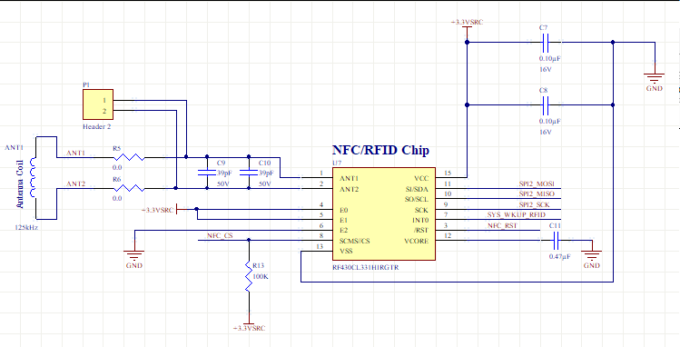
    This is the schematic and I can confirm the board layout follows the schematic correctly.  There is one other slave on this bus (SPI2) but removing the other chip for testing yielded the same result, SO was fixed at 3.3V regardless of startup sequence.

    Is there a possibility that the chip is blown some how?  I could not detect any abnormal heat or smell coming from my board so I assume the RF430CL330 is working correctly.

    Regards,

    Randy

  • Hello Randy,

    The filter caps on VCC should be 1uF and 0.1uF rather than both 0.1uF. I don't think that would cause the issue you see though.

    Before going with the idea that the chip is blown, I would want to verify the same behavior doesn't occur with TI evaluation hardware i.e. the DLP-RF430BP. Unfortunately I neither have a BoosterPack set to SPI mode nor software to test that on my end, as we haven't needed to support SPI mode for years with the device. No one uses it when I2C is significantly better, though it sounds like in your case you have the benefit of a shared bus...

    I can try and adjust a BoosterPack later this week, or if you have one, you can run the same test on your end.
  • Ralph,

    I am not a fan of I2C protocol or implementation but have been forced to use it many times over the years.  I created this board with SPI bus for a specific reason however could bit-bang the I2C if I had to.  It would be disappointing if I had to but at this point I have spent far too much time on this problem.

    Is there a possibility that the SPI bus interface has been eliminated on newer chips and then not documented?

    I do not have any of the eval. packages as the chip looked simple enough to implement, would it do me any good?

    Regards,

    Randy

  • Hello Randy,

    SPI has not been removed from any CL330H version. What I am wondering and need to test on my end is if the SPI doesn't set High-Z correctly which could ultimately be an errata item then. As SPI is horribly inefficient on the CL330H due to very poor timing requirements on a hardware level, almost no one has used it over I2C and thus it's possible there could be such an issue that just wasn't ever identified (I think the one known user didn't have the bus shared...)

    The quick solution if that is the case would be to use a tri-state buffer, which would likely be far easier for you than bit banging I2C.

    I will try and get to testing this later today and see if I can replicate your issue on the hardware I have.
  • Ralph,

    Removed other slave chip on SPI bus and converted GPIO pins to I2C interface.  Made sure CS = 0 when RST was removed (=1) so should have started in I2C mode.

    Attempted several tests using address 0x2B (as E0&E1 are tied to VCC) and still getting nothing from the chip, not even an ACK.

    Is there a start up sequence I am missing?  Do the CS or RST pins require pull ups?  Is VCC == 3.3 not valid as the schematic for the demo shows 3.6?  I am open to anything at this point.

    I have several other slave chips on the board, all on various SPI buses and working perfectly so this is the final chip on this new board but simply cannot get it to respond.

    Is there anything else you can suggest?

    Regards,

    Randy

  • Hello Randy,

    I finally got to run some tests with the device booting in SPI mode allowing the internal resistor to pull the line high as described via DS. In these tests, the MISO line remains at high impedance as specified, and does not output 3.3V.

    Based on this and also the issue you are having with I2C, it sounds like the chip might actually have been damaged, so a chip swap would make sense at this point.

    You may also want to pick up a DLP-RF430BP and MSP-EXP430G2 LaunchPad and then swap your current IC onto it and run our code example on it to see if the device has any issues. If it can't run the TI example code properly, then we can safely assume the device has been damaged in some manner.

    There are no pullups required for /CS or /RST, and /CS has an internal pull-up so if using I2C it needs to be set to ground.
  • Hello Ralph,

    Did alot of clean up testing on the circuit and cleared the problem we discussed.  The chip does not appear to be damaged however, with the SPI bus now dedicated to just the RF430CL330 and the MCU there is something else occurring that I am not sure is correct.

    When Reset is removed with CS tied high, the SCK line now appears to have a 0.9V level on it.  In Idle state (Mode 3) the SCK maintains the 3.3V but when the MCU places a 0V on the SCK line, there is a 0.9V residual remaining.

    Is there anything here that makes sense?

    The chip still does not communicate with the MCU.

    Regards,

    Randy

  • Hello Randy,

    That doesn't make sense at all to me either. SCK shouldn't have anything keeping it elevated like what you described. I wonder if there could be some issue with power or ground for the device where a connection is made fully or maybe something isn't properly tied to a ground plane? That's the only thing that comes to mind...
  • Ralph,

    Outsmarted by a rookie... gave it to one of my junior technicians and it took him about 2 minutes.

    The BOM (and diagram above) indicate the chip is an RF430CL331 which does not support SPI, the BOM was modified by the layout crew without realizing the chip bus was different.  They assumed it was a newer version of 330.

    So now you can close this one, case solved.

    Regards,

    Randy

  • Hi Randy,

    Oh. Yeah, that uh... that'd explain everything...! I didn't notice that either since the schematic model still had the CL330H pin names (which are I2C_Ready/I2C_Signal on the 331H) so slipped by my eyes too. Oh well, happens to all of us at some point :) Best of luck with the rest of the project!