This thread has been locked.

If you have a related question, please click the "Ask a related question" button in the top right corner. The newly created question will be automatically linked to this question.

CCS/RF430FRL152HEVM: Example code of NFC value reading for RF430FRL152H

Part Number: RF430FRL152HEVM
Other Parts Discussed in Thread: RF430FRL152H, RF430CL330H, UNIFLASH, DLP-7970ABP

Tool/software: Code Composer Studio

Hi,

I am using RF430FRL152HEVM kit for NFC communication with mobile phone. I want to perform read and write operation from mobile phone to RF430FRL152HEVM kit.  Can you provide any basic example code so that i could test this functionality with minimum efforts. 

I have not found any example code (firmware) from TI weblink regarding this functionality . 

Thanks,

Anil Garg

  • Hello Anil,

    Details of our NDEF example offerings are discussed in Section 1.4 of our FAQ: http://www.ti.com/lit/pdf/sloa247

  • Hi,

    Thanks for providing response and useful link.

    1. I have tried example from below PATH:
    slac691f\RF430FRL15xH_Projects_v1_5\RF430FRL15xH_Projects_v1_5\RF430FRL15xH_Projects_v1_5\RF430FRL15xH NFC Projects\RF430FRL152H

    I programmed above code in evaluation board and tested with smart phone. I am facing problem that NFC tag is detecting by smart phone and showing the standards name , but not showing data information.


    NDEF mamory:


    // Block 1
    0x03, // NDEF Message present
    0x0B, // Length , 11 bytes
    0xD1, // Record header
    0x01, // type length

    // Block 2
    0x07, // Payload length
    0x55, // Record Type U (URI)
    0x01, // URI header identifier
    0x74, // 't'

    // Block 3
    0x69, // 'i'
    0x2E, // '.'
    0x63, // 'c'
    0x6F, // 'o'

    // Block 4
    0x6D, // 'm'
    0xFE, // TLV terminator
    0x00, // Empty don't care
    0x00 // Empty don't care
    };

    Acording NDEF memory , ti.com should be show in data field after reading from any read write device. i am using smart phone of sony experia M.

    same smart phone is reading data from RF430CL330H evaluation board properly.

    2. Please provide example source code for RF430FRL152 with host controller (SPI/I2C) and ISO15693 interface

    Thanks,
    Anil Garg
  • Hello Anil,

    What application are you using on your smartphone?

    The examples provided within the slac691 are the extent of what we offer, further capability can be developed from them. If you need NFC functionality, then you should use the current project and add I2C code based on our SensorHub Project.
  • In my application i am using a host controller which will write/read data to/from RF430FRL controller using I2C communication. smart phone will read same data from NDEF memory using NFC communication. My question is:
    1. Can i use same I2C sensor library for interfacing with host controller?
    2. WHat is difference between ROM and FRAM mamory? what is the role of block size here?
    3. In example code mentioned in previous post: If ti.com is written in NDEF memory data field then, why is it not showing on smart phone screen , even if NFC tag is detecting by smart phone everytime. ?
    4. Please share any interface example code with Host controller and RF430FRL152/54 for better understanding.

    Thanks,
    AG
  • Hello Anil,

    Anil Garg said:
    1. Can i use same I2C sensor library for interfacing with host controller?

    Not quite as the sensor library has the RF430FRL152H set as the host, not the slave, but you still can get an understanding of configuration requirements.

    Anil Garg said:
    2. WHat is difference between ROM and FRAM mamory? what is the role of block size here?

    ROM is Read Only Memory. It can never be changed, only accessed.

    FRAM is a non-volatile memory that can hold data even after it is powered off. If you want to learn more about FRAM, this FAQ may be good: http://www.ti.com/lit/ml/slat151/slat151.pdf

    Anil Garg said:
    3. In example code mentioned in previous post: If ti.com is written in NDEF memory data field then, why is it not showing on smart phone screen , even if NFC tag is detecting by smart phone everytime. ?

    Again without knowing what smartphone app you are using, I haven't a clue. Smartphone apps vary too much. I need to be able to test it with my phone to be able to offer an inkling of advice.

    Anil Garg said:
    4. Please share any interface example code with Host controller and RF430FRL152/54 for better understanding.

    We don't have such code, sorry.

  • Anil Garg
    3. In example code mentioned in previous post: If ti.com is written in NDEF memory data field then, why is it not showing on smart phone screen , even if NFC tag is detecting by smart phone everytime. ?
    Ralph Jacobi: Again without knowing what smartphone app you are using, I haven't a clue. Smartphone apps vary too much. I need to be able to test it with my phone to be able to offer an inkling of advice.
    Anil Garg:I am using smart phone model neme "Sony Experia M". android application anme: "NFC tool".  if possible kindly share any android application with which you have tested before. i will share the results after test this. 
    Anil Garg
    4. Please share any interface example code with Host controller and RF430FRL152/54 for better understanding.

    Ralph Jacobi: We don't have such code, sorry.

    Anil: Can you share any path for code generator tool?  Because i have very little time to implemant this feature in my application. 

    5. How much maximum length of NDEF mamory is possible as per standard ISO15693 ?

  • Hello Anil,

    Using our NDEF example project from the provided web examples, I used the following two applications with my Samsung Galaxy S7 Active device:

    NFC Tools by wakdev (I presume this is the NFC Tool you are referencing as it was the top result for me under that search within Play Store):

    NFC TagInfo by Michael Roland (Hagenburg Research):

    Both apps had no issue reading the tag.

    Regarding Code Generation tool, that is not something we have, sorry.

    Regarding max NDEF size, that is defined by the NFC Forum, not ISO15693. I believe it is set to be 2^16-1 or 65535 bytes, but I am not positive, you'd have to verify with NDEF standards if curious. However that maximum won't apply for the RF430FRL15xH devices as they are limited by available memory so you are looking at 3kB of NDEF memory maximum and that is if you don't use any other features on the device. After developing your host controller firmware, whatever space is left would be the largest NDEF message that you can use with the device.

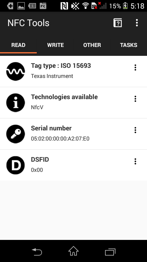
  •  Hi, I have tried multiple times with different smart phone but every time I am able to read only attched messages(screen shots). I am not able to read data (ti.com).  Please confirm that is there any hardware settings for  reading NDEF memory initially. ?


    Can you share source code with which you have tested before..?

    Ralph Jacobi:

    Regarding max NDEF size, that is defined by the NFC Forum, not ISO15693. I believe it is set to be 2^16-1 or 65535 bytes, but I am not positive, you'd have to verify with NDEF standards if curious. However that maximum won't apply for the RF430FRL15xH devices as they are limited by available memory so you are looking at 3kB of NDEF memory maximum and that is if you don't use any other features on the device. After developing your host controller firmware, whatever space is left would be the largest NDEF message that you can use with the device.

    Anil:

    1. Size of FRAM is 2 kB as per data sheet then is it possible to extend NDEF memory size upto 3kB?  

    2. In NDEF message format : length and payload length is allocated by 1 byte of space (as per below message) which is maximum possible upto 255 bytes of length. then how can we define NDEF memory which is greater then 255 bytes in a single variable ? 

    NDEF mamory:


    // Block 1
    0x03, // NDEF Message present
    0x0B, // Length , 11 bytes
    0xD1, // Record header
    0x01, // type length

    // Block 2
    0x07, // Payload length
    0x55, // Record Type U (URI)
    0x01, // URI header identifier
    0x74, // 't'

    // Block 3
    0x69, // 'i'
    0x2E, // '.'
    0x63, // 'c'
    0x6F, // 'o'

    // Block 4
    0x6D, // 'm'
    0xFE, // TLV terminator
    0x00, // Empty don't care
    0x00 // Empty don't care
    };

    Example code (using for testing):

    Main.c:
    
    #include "NDEF.h"
    #include "types.h"
    #include "patch.h"
    #include <rf430frl152h.h>
    
    //*****************************FUNCTION PROTOTYPES********************************/
    void DeviceInit(void);
    //********************************************************************************/
    
    /*********************** SUMMARY **************************************************************************************************
     * This project *only* utilizes the RF stack (ISO15693) on the ROM of the RF430FRL15xH. This setup allows the user to make a
     * custom application that is run from FRAM.  Only the RF13M vector that runs the RF stack needs to be pointing to its
     * ROM location.
     */
    
     /**************************************************************************************************************************************************
    *   Code Space
    ***************************************************************************************************************************************************
    *
    *  Please check the lnk_rf430frl152h_NFC_Only.cmd file to customize how much code space is used for NDEF message ("FRAM_NDEF")
    *  or for code ("FRAM_CODE").  
    *
    **************************************************************************************************************************************************/
    
    /**************************************************************************************************************************************************
    *   Main
    ***************************************************************************************************************************************************
    *
    * Brief :		Program entry.
    *
    * Param[in] :   None
    *
    *
    * Param[out]:   None
    *
    * Return :
    *
    **************************************************************************************************************************************************/
    
    void main()
    {
    
        WDTCTL = WDTPW + WDTHOLD;                   // Stop watchdog
    
        // ROM RF13M module setup ** The following three lines are needed for proper RF stack operation
        DS = 1; 									// ROM variable needs to be initialized here
        asm ( " CALL #0x5CDA "); 					// Call ROM function ( Initialize function pointers)
        asm ( " CALL #0x5CAC "); 					// Call ROM function ( Check part configuration)
    
    
    	initISO15693(CLEAR_BLOCK_LOCKS);  // clear all block locks
    	//initISO15693(0);					// leave block locks as they are set in FRAM
    
    	//JTAG is set to be disabled in this function call
    	DeviceInit();
    
    	while(1)
    	{
            // Enter application code here...
    		__bis_SR_register(LPM3_bits + GIE);
    	}
    }
    
    /**************************************************************************************************************************************************
    *  DeviceInit
    ***************************************************************************************************************************************************
    *
    * Brief : Initialize the clock system and other settings
    *         Patchable function
    *
    * Param[in] :   parameters:  has these independent options
    *                            INITIALIZE_DEVICE_CLOCK_SYSTEM - initializes the clock system
    *                            POPULATE_INTERRUPT_VECTOR_IN_INITIALIZATION - populate the default interrupt vectors and recalculate their CRC
    *
    * Param[out]:  None
    *
    * Return  None
    *
    * Patchable :   Yes
    **************************************************************************************************************************************************/
    void DeviceInit(void)
    {
    	P1SEL0 = 0xF0; //keep JTAG
    	P1SEL1 = 0xF0; //keep JTAG
    //	P1SEL0 = 0x00; //no JTAG
    //	P1SEL1 = 0x00; //no JTAG
    
        P1DIR &= ~0xEF;
        P1REN = 0;
    
        CCSCTL0 = CCSKEY;                        // Unlock CCS
    
        CCSCTL1 = 0;                             // do not half the clock speed
        CCSCTL4 = SELA_1 + SELM_0 + SELS_0;      // Select VLO for ACLK and select HFCLK/DCO for MCLK, and SMCLK
        CCSCTL5 = DIVA_2 + DIVM_1 + DIVS_1;      // Set the Dividers for ACLK (4), MCLK, and SMCLK to 1
        CCSCTL6 = XTOFF;                         // Turns of the crystal if it is not being used
        CCSCTL8 = ACLKREQEN + MCLKREQEN + SMCLKREQEN; //disable clocks if they are not being used
    
        CCSCTL0_H |= 0xFF;                       // Lock CCS
    
      return;
    }


    //#pragma vector = RFPMM_VECTOR
    //__interrupt void RFPMM_ISR(void)
    //{
    //}
    //
    //#pragma vector = PORT1_VECTOR
    //__interrupt void PORT1_ISR(void)
    //{
    //}
    //
    //#pragma vector = SD_ADC_VECTOR
    //__interrupt void SD_ADC_ISR(void)
    //{
    //}
    //
    //#pragma vector = USCI_B0_VECTOR
    //__interrupt void USCI_B0_ISR(void)
    //{
    //}
    //#pragma CODE_SECTION(RF13M_ISR, ".fram_driver_code")  // comment this line for using ROM's RF13M ISR, uncomment next one, see .cmd file for details
    #pragma CODE_SECTION(RF13M_ISR, ".rf13m_rom_isr") 		// comment this line for creating a custom RF13M ISR that will exist in FRAM, bypassing ROM's, uncomment previous
    #pragma vector = RF13M_VECTOR
    __interrupt void RF13M_ISR(void)
    {
    	// Right now this vector is pointing to the ROMs firmware location that runs the RF stack. 
        // Entering code here will, without changing the CODE_SECTION lines
    	// above, will cause an error.
        // Changing the code section above will cause the ROM RF stack to be bypassed.  New handler will need to be created.
    }
    
    //#pragma vector = WDT_VECTOR
    //__interrupt void WDT_ISR(void)
    //{
    //}
    //
    //#pragma vector = TIMER0_A1_VECTOR
    //__interrupt void TimerA1_ISR(void)
    //{
    //}
    //
    //#pragma vector = TIMER0_A0_VECTOR
    //__interrupt void TimerA0_ISR(void)
    //{
    //}
    //
    //#pragma vector = UNMI_VECTOR
    //__interrupt void UNMI_ISR(void)
    //{
    //}
    //
    //#pragma vector = SYSNMI_VECTOR
    //__interrupt void SysNMI_ISR(void)
    //{
    //}


    NDFE.c
    
    
    //This project is based on the RF430FRL152H.  However it will work as well on the RF430FRL154H.
    //However ROM_SENSOR_SUPPORT_DISABLED (or ROMSensorSupportEnable see above for both )must be set in the firmware system control register.  This is forced automatically on the RF430FRL154H.
    //This setting is needed to disable the ROM which uses block 0... as virtual registers, however this memory is needed for NDEF purposes.
    #define FIRMWARE_CONTROL_ADDRESS 	0xF867
    #pragma RETAIN(Firmware_System_Control_Byte);
    #pragma location = FIRMWARE_CONTROL_ADDRESS
    //This variable needs to be kept declared and as "volatile" for the BlockLockROM_Patched function to work properly.  Assignment can be changed however.
    volatile const u08_t Firmware_System_Control_Byte = ROM_SENSOR_SUPPORT_DISABLED + EROM_EUSCI_SUPPORT_DISABLED + NFC_BRIDGE_DISABLED + FOUR_BYTE_BLOCK + FIRST_ISO_PAGE; //0x7F,		// this value sets the firmware system control register
    
    // ROM variables - DO NOT CHANGE !!!
    // Declared to protect from use by compiler
    /********************************************/
    #pragma RETAIN(DS)
    #pragma location = 0x1C00
    u08_t DS;
    #pragma RETAIN(RF)
    #pragma location = 0x1C6A
    const u08_t RF;
    #pragma RETAIN(NRX)
    #pragma location = 0x1CA4 //rx
    const u08_t NRX[34];
    #pragma RETAIN(NTX)
    #pragma location = 0x1CC6 //tx
    const u08_t NTX[33];
    #pragma RETAIN(EL)
    #pragma location = 0x1CF2
    const u08_t EL;
    #pragma RETAIN(PF)
    #pragma location = 0x1C0A
    const u16_t PF[48];
    /********************************************/
    
    /*
     * This is an NDEF message: www.ti.com
     * This can be made longer and edited as necessary.  However it is limited to the first page (about 968 bytes),
     * the second page is mainly used for patch firmware, but can be read over NFC as well, with proper commands.
    */
    
    #define NDEF_START_ADDRESS	0xF868
    #pragma RETAIN(NFC_NDEF_Message);
    #pragma location = NDEF_START_ADDRESS;																	// the location of the address
    
    const u08_t NFC_NDEF_Message[21] = {
    
    		// Block 0
    		0xE1, 		// NDEF Magic Number
    		0x40, 		// Version Number, read/write access conditions
    		0x79,  //0x7E,		// 1008 bytes / 8 = 126 blocks
    		0x00,//0x04,//8 byte extended memory //0x00,		// does not support read multiple blocks (limited to only 3 blocks)
    
    		// Block 1
    		0x03,		// NDEF Message present
    		0x0B,		// Length , 11 bytes
    		0xD1,		// Record header
    		0x01,		// type length
    
    		// Block 2
    		0x07,		// Payload length
    		0x55,		// Record Type U (URI)
    		0x01, 		// URI header identifier
    		0x74,		// 't'
    
    		// Block 3
    		0x69,		// 'i'
    		0x2E,		// '.'
    		0x63,		// 'c'
    		0x6F,		// 'o'
    
    		// Block 4
    		0x6D,		// 'm'
    		0xFE,		// TLV terminator
    		0x00,		// Empty don't care
    		0x00		// Empty don't care
    };
    
    /**************************************************************************************************************************************************
    *  initISO15693
    ***************************************************************************************************************************************************
    *
    * Brief : Initializes the RF Stack
    *
    * Param[in] :   parameter - the configuration to setup the ISO15693 (option to clear the lock blocks)
    *
    * Param[out]:   None
    *
    * Return        None
    **************************************************************************************************************************************************/
    void initISO15693(u16_t parameters )
    {
    
      RF13MCTL |= RF13MTXEN + RF13MRXEN + RF13MRFTOEN; 	// set up rx and tx functionality on RF13M module
      // enable interrupts  ** Do not change the following two lines, needed for proper RF stack operatoin
      RF13MINT |= RF13MRXIE + RX13MRFTOIE;  			// enable interrupts on RX and on timeout and over and under flow checking
    
      if (parameters & CLEAR_BLOCK_LOCKS )
      {
        memset ((u08_t *) FRAM_LOCK_BLOCKS, 0xFF, FRAM_LOCK_BLOCK_AREA_SIZE);     //block is locked with a zero bit, clears FRAM and RAM lock blocks
      }
    
    //  BlockLockAPI(3, LOCK_BLOCK);  //Test this API
    //
    //  BlockLockAPI(3, CHECK_LOCK);  //Test this API
    }
    
    /**************************************************************************************************************************************************
    *  BlockLockAPI
    ***************************************************************************************************************************************************
    *
    * Brief : Locks a block either in FRAM or in RAM.
    *
    * Param[in] :   block - The block to lock.  In 4-byte mode this will lock two blocks and depends on the page selected.
    *
    * Param[out]:   None
    *
    * Return        None
    **************************************************************************************************************************************************/
    u16_t BlockLockAPI(u16_t block, u08_t checkLock)
    {
    	u16_t locked;
    
    	locked = BlockLockROM_Patched(block, checkLock );
    	return locked;
    }


    lnk_rf430frl152h_NFC_Only.cmd:
    
    /****************************************************************************/
    /* Specify the system memory map                                            */
    /****************************************************************************/
    
    MEMORY
    {
        SFR                     : origin = 0x0000, length = 0x0010
        PERIPHERALS_8BIT        : origin = 0x0010, length = 0x00F0
        PERIPHERALS_16BIT       : origin = 0x0100, length = 0x0100
        RAM                     : origin = 0x1C00, length = 0x1000
    
        //ROM ISRs, starting points, length not correct
        RF13M_ROM_ISR			: origin = 0x54D0, length = 0x0002
    
        // code area, can be increased /  decreased
        // FRAM_NDEF + FRAM_CODE lengths must equall 0x768 (with FRAM_NDEF starting at 0xF868)
        // Two sections together in the range of 0xF868-0xFFCF 
        FRAM_NDEF               : origin = 0xF868, length = 0x0068 // ends at 0xF8CF - NDEF memory section
        FRAM_CODE               : origin = 0xF8D0, length = 0x0700 // ends at 0xFFCF - Firmware memory section
        JTAGSIGNATURE           : origin = 0xFFD0, length = 0x0004, fill = 0xFFFF
        BSLSIGNATURE            : origin = 0xFFD4, length = 0x0004, fill = 0xFFFF
        INT00                   : origin = 0xFFE0, length = 0x0002
        INT01                   : origin = 0xFFE2, length = 0x0002
        INT02                   : origin = 0xFFE4, length = 0x0002
        INT03                   : origin = 0xFFE6, length = 0x0002
        INT04                   : origin = 0xFFE8, length = 0x0002
        INT05                   : origin = 0xFFEA, length = 0x0002
        INT06                   : origin = 0xFFEC, length = 0x0002
        INT07                   : origin = 0xFFEE, length = 0x0002
        INT08                   : origin = 0xFFF0, length = 0x0002
        INT09                   : origin = 0xFFF2, length = 0x0002
        INT10                   : origin = 0xFFF4, length = 0x0002
        INT11                   : origin = 0xFFF6, length = 0x0002
        INT12                   : origin = 0xFFF8, length = 0x0002
        INT13                   : origin = 0xFFFA, length = 0x0002
        INT14                   : origin = 0xFFFC, length = 0x0002
        RESET                   : origin = 0xFFFE, length = 0x0002
    }
    
    /****************************************************************************/
    /* Specify the sections allocation into memory                              */
    /****************************************************************************/
    
    SECTIONS
    {
        GROUP(ALL_FRAM)
        {
           GROUP(READ_WRITE_MEMORY)
           {
              .TI.persistent : {}                /* For #pragma persistent            */
              .cio        : {}                   /* C I/O buffer                      */
              .sysmem     : {}                   /* Dynamic memory allocation area    */
           }
    
           GROUP(READ_ONLY_MEMORY)
           {
              .cinit      : {}                   /* Initialization tables             */
              .pinit      : {}                   /* C++ constructor tables            */
              .init_array : {}                   /* C++ constructor tables            */
              .mspabi.exidx : {}                 /* C++ constructor tables            */
              .mspabi.extab : {}                 /* C++ constructor tables            */
              .const      : {}                   /* Constant data                     */
           }
    
           GROUP(EXECUTABLE_MEMORY)
           {
              .text       : {}                   /* Code                              */
           }
        } > FRAM_CODE
    
        .rf13m_rom_isr		: {} > RF13M_ROM_ISR type = DSECT
    
        .jtagsignature : {} > JTAGSIGNATURE   /* JTAG Signature                    */
        .bslsignature  : {} > BSLSIGNATURE    /* BSL Signature                     */
        .jtagpassword                         /* JTAG Password                     */
    
        .bss        : {} > RAM                /* Global & static vars              */
        .data       : {} > RAM                /* Global & static vars              */
        .TI.noinit  : {} > RAM                /* For #pragma noinit                */
        .stack      : {} > RAM (HIGH)         /* Software system stack             */
    
        /* MSP430 Interrupt vectors          */
    
        .int00       : {}               > INT00
        .int01       : {}               > INT01
        .int02       : {}               > INT02
        .int03       : {}               > INT03
        .int04       : {}               > INT04
        RFPMM        : { * ( .int05 ) } > INT05 type = VECT_INIT
        PORT1        : { * ( .int06 ) } > INT06 type = VECT_INIT
        SD_ADC       : { * ( .int07 ) } > INT07 type = VECT_INIT
        USCI_B0      : { * ( .int08 ) } > INT08 type = VECT_INIT
        ISO          : { * ( .int09 ) } > INT09 type = VECT_INIT
        WDT          : { * ( .int10 ) } > INT10 type = VECT_INIT
        TIMER0_A1    : { * ( .int11 ) } > INT11 type = VECT_INIT
        TIMER0_A0    : { * ( .int12 ) } > INT12 type = VECT_INIT
        UNMI         : { * ( .int13 ) } > INT13 type = VECT_INIT
        SYSNMI       : { * ( .int14 ) } > INT14 type = VECT_INIT
      	.reset       : {}               > RESET  /* MSP430 Reset vector         */
    }
    
    /****************************************************************************/
    /* Include peripherals memory map                                           */
    /****************************************************************************/
    
    -l rf430frl152h.cmd

    Thanks,

    Anil 

  • Hello Anil,

    That result makes me think the tag doesn't have the NDEF project correctly loaded or implemented. Did you make any changes to it?

    The example project used was the one located at:

    [System Location]\slac691f\RF430FRL15xH_Projects_v1_5\RF430FRL15xH_Projects_v1_5\RF430FRL15xH_Projects_v1_5\RF430FRL15xH NFC Projects\RF430FRL152H

    Regarding NDEF space, sorry for my typo on FRAM, I meant maximum 2kB space.

    I should also mention if the NDEF data can be volatile (i.e. disappear when power is off) then the 4kB RAM can be used as well, though that would likely require a battery powered application.

    Anil Garg said:
    In NDEF message format : length and payload length is allocated by 1 byte of space (as per below message) which is maximum possible upto 255 bytes of length. then how can we define NDEF memory which is greater then 255 bytes in a single variable ? 

    The NFC Forum specifications for NDEF messaging outlines how to declare NDEF messages larger than 255 bytes. Please refer to them for understanding of how structure the message to support larger than 255 bytes.

  • 1. As per NDEF memory i have shared in previous mail with you: message should be display ti.com but as per screen shot shared by you , its showing http://www.ti.com. why is looking some diffrence if we are refering same source code?

    2. I am using Code Composer Studio 7.3.0 IDE . I have exported CCS source code in one directory , complied succesfully and programmed with MSP FET430UF. same thing i have varified by programming with UNIFLASH tool also. Switch S6 position is kept on supply position. SV7 jumper is shorted. same thing i have varified with USB , JTAG as well as RF supply. same process i have repeated with different smart phones and receiving same results as shared with you.


    I dont know the exact reason , why is it not working properly ?.

    Thanks,

    Anil
  • Hello Anil,

    The screenshot you sent didn't display any data.

    If you are wondering why you get http://www.ti.com instead of just ti.com, that is very easy to explain.

    This portion of the NDEF message is why:

            0x55,       // Record Type U (URI)
            0x01,       // URI header identifier

    The URI identifier code is 0x01 which maps to http://www/. Therefore, the http://www. information is automatically appended by the Android application due to the URI identifier used as part of the NDEF message.

    Refer to official NDEF specs for URI messaging for more detail.

  • I am using Code Composer Studio 7.3.0 IDE . I have exported CCS source code in one directory , complied succesfully and programmed with MSP FET430UF. same thing i have varified by programming with UNIFLASH tool also. Switch S6 position is kept on supply position. SV7 jumper is shorted. same thing i have varified with USB , JTAG as well as RF supply. same process i have repeated with different smart phones and receiving same results as shared with you.

    Please provide any direction for troubleshooting the problem.. any switch position issue ????  Or any linker file issue ?? Or something else ??

  • Hello Anil,

    I don't understand the problem fully but Section 2.3 of the EVM User's Guide covers correct switch setups, that may help: http://www.ti.com/lit/ug/slau607b/slau607b.pdf

  • That's I have already done.. can I doubt on evaluation board also ?
  • Hello Anil,

    I read through your thread again and I see a lot of conflicts about what the problem is.

    I've seen you say everything from you can't read the NDEF to having gotten http://www.ti.com

    What is the exactly problem situation right now? Is it identical to screenshot from this post: e2e.ti.com/.../2541323 where you can read the tag but there is no NDEF data present?

  • I received a evaluation kit RF430FRL152HEVM from TI. During testing of NFC communication  by smart phone (sony experia M with NFC tool application) with default programme (which came with evaluation board) it was obserbed that i was only able to read tag information,  not the  NDEF memory. 

    Then i re-prograamed the controller using MSP FET 430 (CCS 7.3.0 by source code given below example path), But still i am facing  same issue. 

    example from below PATH:

    slac691f\RF430FRL15xH_Projects_v1_5\RF430FRL15xH_Projects_v1_5\RF430FRL15xH_Projects_v1_5\RF430FRL15xH NFC Projects\RF430FRL152H

    waiting for your suggestion.

    thanks,

    Anil

  • Hello Anil,

    Do you have the hardware needed to use the RF430FRL152HEVM GUI? We can check for if settings were correctly programmed using that.
  • Yes.. I am using "MSP430 USB-Debug-interafce MSP-FET430UIF " for programming the card. please find below screen shot of settings and configuration.    .

  • Hello Anil,

    I mean the RF430FRL152HEVM GUI which needs a reader device as well like the formerly available TRF7970AEVM or now currently the DLP-7970ABP with the MSP-EXP430G2 LaunchPad.

    The GUI is pictured here:

  • No.. I am not using any GUI because of not availablity of reader device... Is there any dependecy of that one?
  • Hello Anil,

    Not normally, but I don't know of another method to debug this issue. You are the only person to ever have a problem with that example and I have no explanation why and cannot re-create it here. The GUI would help give me some more info to maybe figure out what is wrong.
  • Dear Ralph,

    Still i am looking solution of problem.

    I have tested with different smart phone (like Sony Experia M , Samsung Galaxy etc) as well as diffrent android applications (like NFC tool, NFC Reader etc) with tested evaluation board ( RF430FRL152HEVM kit which was tested by TI bangalore team) , But still at my end i am not able to read NDEF memeory and getting same results as shared before in traling communication.

    I would like to know that, is there dependency of issue on android version or mobile phone support ? Because both mobile phones are NFC supportable and i am able to read NDEF data of ISO 1443-4 Tag (RF430CL330H) succesfully .

    If you need then i can also share the testing vedio .

    Thanks,
    Anil Garg
  • Hello Anil,

    Sometimes there can be a dependency on Android phones as each phone runs it's own NFC stack so operation with Sony vs Samsung vs Google vs LG will have some variance, however that rarely affects reading tags. Usually that only affects NFC modes like Peer-to-Peer and Card Emulation.

    One thing that can tie up many smartphones is that the RF430FRL152H defaults as 8-byte mode unless programmed to be in 4-byte mode, and not all phones support reading the 8-byte mode. However, the NDEF example provided with our firmware examples handles setting the device to 4-byte mode, so if it is correctly used, that should not be an issue. Using the RF430FRL152HEVM GUI would help identify this very easily as the GUI only works for 8-byte mode and will pop up a warning if you try and read the registers when it is in 4-byte mode.

    Feel free to share videos with a couple phones and apps, I can comment on what I see on them.

  • Mobile phone ,which i am using , is 2013 model.. will it support IEC 15693 NFC standard?
  • Hello Anil,

    It should though I am not sure how well NDEF was defined for ISO15693 then so potentially that could be why? I wasn't working on NFC in 2013 so can't say for sure one way or the other :)

    Can you try with any phones from the last 2-3 years?
  • Hi Ralph,

    Thanks for your valuable inputs and support. 

    Problem was related from the compatibility of mobile phone reader as per standard IEC15963. 

    Now it is working fine. 

    some more query:

    1. What is procedure to declare any global RAM variable in RF430FRL15x MSP controller. ? i am able to declare local variable but not accessible RAM using any global variable . Why?

    2. How can i use the feature of RF air programming ? I want to programme RF430FRL15x controller using the .out file generated in example code.I have tried with DLP-7970ABP with the MSP-EXP430G2 LaunchPad using GUI application (suggested by you in last communication). 

    Thanks,

    Anil


    Thanks,

    Anil

  • Hello Anil,

    Can you start a new thread for these queries? This thread is already quite long, and both of those questions are not in line with the topic.