This thread has been locked.

If you have a related question, please click the "Ask a related question" button in the top right corner. The newly created question will be automatically linked to this question.

RF430FRL152H: RF430FRL152H antenna does not work

Part Number: RF430FRL152H

Hi,

When I finished the manual soldering, I used the smart phone with NFC to approach the circuit board. The smart phone was equipped with RF430FRL152H Demo App. At the beginning, data on the mobile phone showed that the antenna part capable of PCB could work.After about 10 times, no matter how close the phone is to the circuit board

, the antenna began to fail, and there was no response on the phone, and the voltage measured on the VDDSW jumped between 0.3-1.4v, not up to 1.5v.This phenomenon is repeatable, what reason for this?How do I solve this problem?

Thanks very much!

  • Hello,

    I don't have enough information to offer an answer, please give me the following details:

    1) Is this is a passively powered system?
    2) What is the antenna size of your antenna?
    3) Does your system use a thermistor like done for the TI design which uses the Demo App?
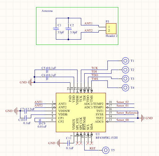
    4) Can you share the schematic for your custom board?
    5) What method did you use for antenna tuning?
  • Hello,

    I'm sorry that I didn't provide enough information on this issue.

    1) yes, this is a passively powered system.

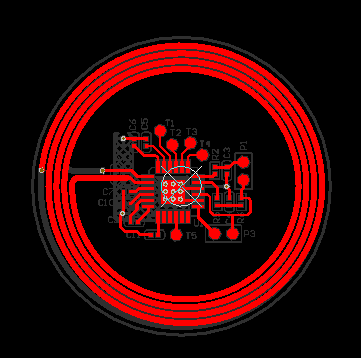
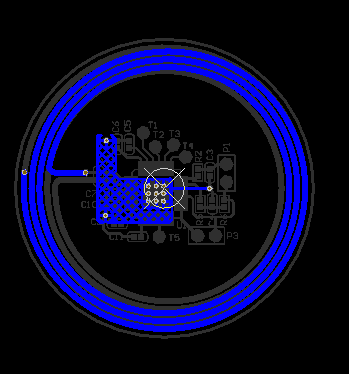
    2) Circular antenna with maximum diameter of 23.6mm.

    3)yes, the  thermistor was used, but I did not solder  the ADC input components including  the thermistor.Just test the power.

    4)sure.The PCB shows that antenna has 7 turns: 4 turns on the top,3 turns on the bottom.

    5)The antenna part has not been tested at the present stage, and it is ready to test the frequency, inductance and so on with the network analyzer.

    The voltage on the VDDSW end is unstable, always less than 1,5V. ON the RF430_TMPSNS_EVM_A,The voltage on the VDDSW end  is about 1.55V,quite stably.

    So,I want to know the really reason. 

     Best Regards!

  • Hello Hao,

    Few comments on schematic:

    1) Is there a 1uF cap between SVSS and VSS? This is recommended for proper ADC operation if using SVSS.
    2) There should be a 10nF decoupling cap on RST.

    I don't think either of those problems explains the VDDSW readings though.

    Looking at your antenna, and making an assumption of trace width = 10 mil, I calculated the theoretical inductance to be 2.85 uH.

    With that value, you'd be looking at needing approximately 48 pF of capacitance based on our antenna tuning guide: www.ti.com/.../sloa217a.pdf

    Given the RF430FRL152H already offers an internal capacitance of 35 pF, you only need to add ~13 pF more capacitance to get to the right resonance levels. However, I am not seeing anything close to that populated for your PCB. You have a 33 pF and 3.9 pF, so your antenna is likely tuned very far out of range. If that is the case, then it is likely not getting enough RF coupling to draw the requisite power.

    I would recommend, if you do have access to a network analyzer or even just a spectrum analyzer, trying to determine the inductance of your coil and tuning it per the app note. Though honestly I am pretty confident that just swapping those 2 caps for something in the 12-15 pF range should at least get your VDDSW reading up to expected levels should the tuning be the problem.
  • Hello,Ralph 

    Thank you for reply!

    Now I have an another question for RF430FRL152H.I adjusted the capacitance to make the  frequency of the antenna  working on 13.7MHz(nearly).But,the IC's voltage is about 0.2V.

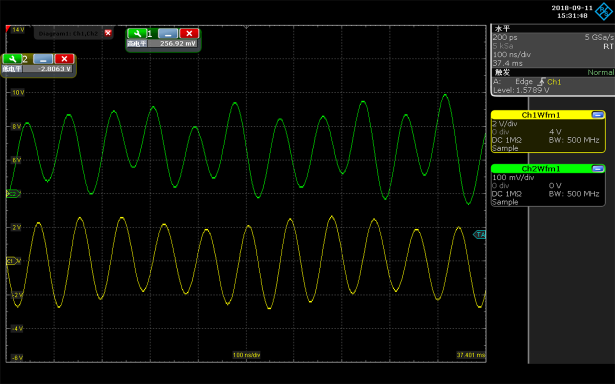
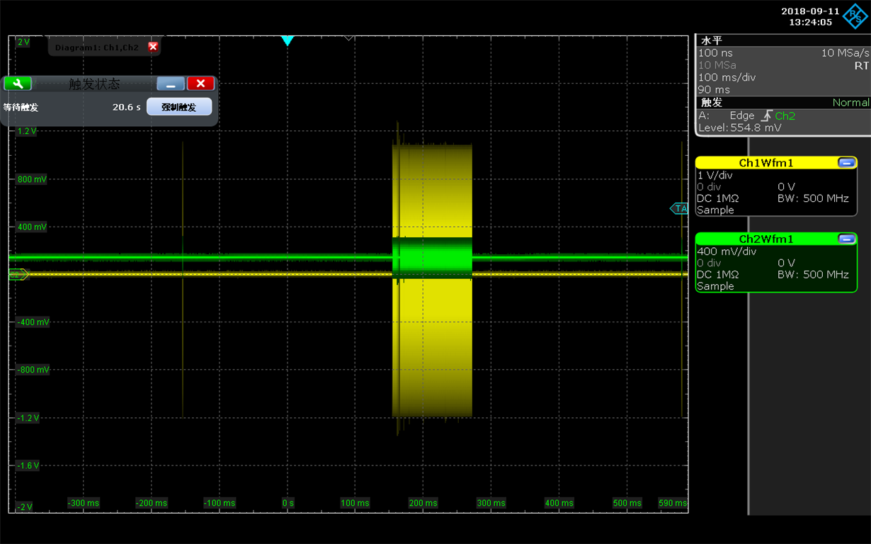
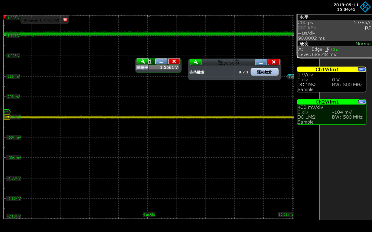
    When I check the waveform,it seems that Rectifier part of RF13M Module has not work.

    CH1 : antenna voltage

    CH2: VDDSW,

    THE nowmal waveform of  VDDSW(test on EVM) 

    Maybe RF430FRL152H is damaged,I have tried two different PCBs,But the problem remains.I have no idea for the reason.

    Can you tell me the possible reason?Thanks a lot!

    Best regards!

  • Hello Hao,

    Honestly I am at a bit of a loss as well. I've never seen such behavior before. I reviewed your schematic again but I don't see anything missing that would impact that.

    Have you checked the solder connections well? That's the only thing I can think of. ANT2 and VDDSW are next to each other so a solder bridge could explain it.