This thread has been locked.

If you have a related question, please click the "Ask a related question" button in the top right corner. The newly created question will be automatically linked to this question.

Save power through time synchronism

Other Parts Discussed in Thread: CC1310

Hi

My customer use Sub1G transceiver do peer to peer connection, both side has low power demand.

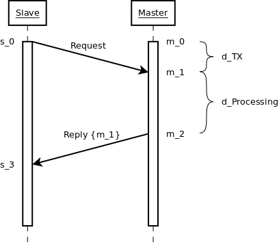
They found it bring high current at this situation when transmitter send packet many times until receiver wake up from sleep stage. In order to save both side power, I think time synchronization is a good method to solve the problem.

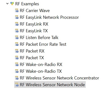
Which CC1310 example project has time synchronization?  or do it by TI Mac beacon? Could you kindly give your advice? Thanks.

  • Hi Daniel,

    here is a suggestion how to synchronize a slave to a master without the need of measuring anything. It's basically the same algorithm as NTP uses:

    In this example we have a master and a slave and we want to synchronize the slave clock to the master’s clock (radio timer RAT). Both clocks run with the same tick rate, but the slave clock has a certain initial offset T_0 relative to the master. Assuming that m_n and s_n specify absolute timestamps on the master and slave, respectively, we get the relationship:

    (1) s_n = m_n + T_0

    Initially, the slave doesn’t know T_0 and hence, m_n and s_n are different time domains. The following sequence diagram shows the synchronization process.

    The slave sends a synchronization request to the master and sets s_0 as an absolute start trigger for the TX command. After a short delay (RF frontend ramp-up), the RF core starts transmitting the preamble and the syncword. The time between firing the start trigger at the TX side and the receiver detects the syncword is named d_TX. It is a fixed value for a given RF configuration and could be measured. Here in this example, we measure it indirectly.

    The master receives the message and at the time m_1 = s_0 + d_TX (syncword found), it appends the receiver timestamp to the packet.

    After a short, predefined time d_Processing, the master responds to the request with a reply message. It sets the TX command start trigger to an absolute time m_2 and includes m_1 into the packet payload:

    (2) m_2 = m_1 + d_Processing

    When the client receives the reply at s_3, it has the following timing information and can calculate the initial clock offset T_0:

    • s_0: Request sent by the client
    • m_1: Request received by the master
    • s_3: Reply received by the client
    • d_Processing: A fixed delay for message processing on the master

    From (1), we know that:

    (3) T_0 = s_0 - m_0

    We don’t know m_0, but we know its offset to m_1 which is d_TX:

    (4) m_0 = m_1 - d_TX

    With (3) and (4) we get:

    (5) T_0 = s_0 - (m_1 - d_TX)

    We still don’t know d_TX, but we know that it is included into the round-trip time s_3 - s_0 as follows:

    (6) s_1 - s_0 = 2 * d_TX + d_Processing

    With the help of (6) we can rewrite (5) to:

    (7) T_0 = s_0 - (m_1 - (s_3 - s_0 - d_Processing) / 2)

    and finally obtain T_0. This value must now be added to any further RF operation on the client.

    All timing values are in the Radio Timer domain of the RF core.

    It is possible to optimize that approach: Since the offset d_TX depends only on the RF settings, it is sufficient to measure it only once during development. Then it can be compiled into the application and only one message sent by the master at is necessary to synchronize all slaves at once. Then the master could send (periodic) beacon messages and include its TX timestamp.

    [EDIT] Updated the image and the description.

  • Hi Richard,

    Many thanks for so professional explanation. Make it simple, which project or command already has synchronization mechanism? Thanks. 

  • Hi Daniel,

    we don't have an example for that, but you can merge the RF Packet RX and TX examples into one. Here are some example code snippets that show the essential parts. I didn't test though, yet, but it should work.

    When sending a timestamp message at a certain time, we use txTimestamp as an absolute start trigger, but include it also into the packet payload:

    // Convenience macro
    #define RF_convertMsToRatTicks(milliseconds) \
    (((uint32_t)(milliseconds)) * 1000 * 4)
    
    // Exported from SmartRF Studio
    rfc_CMD_PROP_TX_t txCommand;
    
    // Set a time in the near future (5ms)
    uint32_t txTimestamp = RF_getCurrentTime() + RF_convertMsToRatTicks(5);
    
    // Set txTimestamp as an absolute start trigger
    txCommand.startTrigger.triggerType = TRIG_ABSTIME;
    txCommand.startTime = txTimestamp;
    
    // Include it also into the payload
    uint32_t payload[1] = { txTimestamp };
    txCommand.pPkt = (uint8_t*)&payload[0];
    txCommand.pktLen = sizeof(payload);

    When receiving this packet, the receiver must read the timestamp from the packet payload, but must also configure the RF core to append a timestamp to each received packet. This is the time when the RF core raises the signal “Synchronization found” and we choose the name rxTimestamp:

    // Exported from SmartRF Studio
    rfc_CMD_PROP_RX_t rxCommand;
    
    // Append RX timestamp to the payload
    RF_cmdPropRx.rxConf.bAppendTimestamp = 1;
    
    // The code to execute the RX command and to setup
    // the RX data queue is not shown here.
    
    // When reading the packet content from the
    // RX data queue, rxTimestamp is behind the payload:
    rfc_dataEntryGeneral_t* currentDataEntry = RFQueue_getDataEntry();
    // Assuming variable length
    uint8_t packetLength = *(uint8_t*)(&currentDataEntry->data);
    uint8_t* packetDataPointer = (uint8_t*)(&currentDataEntry->data + 1);
    uint32_t rxTimestamp;
    memcpy(&rxTimestamp, &packetDataPointer + packetLength, 4);
    
    // The TX timestamp is found in the payload
    uint32_t txTimestamp;
    memcpy(&txTimestamp, &packetDataPointer, 4);