This thread has been locked.

If you have a related question, please click the "Ask a related question" button in the top right corner. The newly created question will be automatically linked to this question.

CC1310: chip not recognized by debugger

Part Number: CC1310
Other Parts Discussed in Thread: CC1350

Hello!

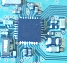
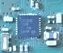
I made a new version of my custom board with cc1310 4x4 and it's not working (chip not recognized by CCS, Smart RF...).

My previous board works fine. Changes in new version: 24 MHz crystal moved, 0 Ohm resistors removed, antenna changed.

Voltages on cc1310 pins looks correct:

11 (VDDS) - 3.17V

12 (DCOUPL) - 1.27V

18 (DCDC_SW) - 1.67V

19 (VDDS) - 3.15V

21 (NRESET)  - 2.86V

27 (VDDS) - 3.17V

28 (VDDR) - 1.67V

32 (VDDR) - 1.65V

I checked connection between JTAG/RESET pins on cc1310 and debug probe (i used cc1350 LP) - it's ok.

I tried to remove 24 MHz crystal (to force internal RC OSC) - no success, chip still not recognized.

What else can i check?

My gerbers in attach (cc1310 part is on bottom): WiFi_CC1310_BridgeV5.zip


  • Hi,

    I suspect the issue with JTAG connections. Could you please recheck?
    You might have some cold joints (solder) on your board. You may touch up the Pins and check again.
    Did you assemble the board manually?

    Thanks,
    PM
  • Hello! Thank you for a quick answer!
    I checked it many times and rechecked now. I also checked that JTAG pins are not connected with each other and VCC/GND.
    I can give you voltages on JTAG pins:
    13 (TMSC) 2.91V
    14 (TCK) 2.91V
    15 (TDO) 1.08V
    16 (TDI) 1.08V
    Yes, boards (2) assembled manually. Both have the same problem.
  • Hi,

    Did you check and compare these voltage levels with your Previous board (working)?
    Did you measure these levels on the Pins of the Chip or on the traces? If the chip is not soldered properly then the pins may not be contacting the traces.
    I had the same issue (Chip not recognized by SmartRF Studio) some time back, I debugged and found that the issue was with one of the JTAG lines not connected to the chip properly.

    Thanks,
    PM
  • Yes, i compared and it's the same.
    I measured these levels on the pins using thin wire.
  • Hi,

    Would it be possible to swap the chips (from Good board to Band board and vice versa) and try?

    Thanks,
    PM
  • Is J6-J7-J8 the Jtag connector? Do you also connect ground and the reset signal?
  • It's not easy, and i do not think, that the problem is on chip side. I assembled 4 boards in one time with chips from one tape. 2 boards (with old design) works fine.
  • 1. Yes,
    J6 - RESET
    J7 - TDI, TDO, TCK
    J8 - TMS
    Yes, Ground, VCC and Reset are connected. Ground and VCC comes from USB connector on the top of the board.

    2. Today i assembled another board with the similar design (but not the same) and found, that DCDC_SW not working. Here the voltages:

    11 (VDDS) 3.33

    12 (DCOUPL) 1.31

    13 (TMSC) 3.3

    14 (TCK) 3.3

    15 (TDO) 0

    16 (TDI) 0

    18 (DCDC_SW) 0.1

    19 (VDDS) 3.33

    21 (NRESET) 3

    27 (VDDS) 3.33

    28 (VDDR) 0.1

    32 (VDDR) 0.1

  • This sounds very much as a hardware/ assembly issue.

    - Have you done any changes to the DCDC part of the design (components connected to DCDC_SW)? Are those correct compared to the ref design? The layout does not look fully optimal, on this part, following the ref design gives best result.

    - The voltages sounds good (except for VDDR on the latest board).

    - I assume that in this case the chip is not programmed in production so the chip is not trying to run a program.

    Cases like this is difficult to debug remote since we don't have the hardware in front of us.
  • No i have not. I just copied layout and components from this ref. design:
    www.ti.com/.../swrc327

    May be few vias slightly moved.
    If i made a mistake, can you point me to it?

    Ref. design board (working)

    My board (not working):

  • Hi,

    Layout looks OK from the Pictures.

    As TER mentioned, it is very difficult to debug from Remotely.

    It is better to Swap the chips from the Working Board to the Non-Working board and vice-versa to find the root cause (Hardware issue/Chip issue)

    Thanks,
    PM
  • Hello!
    Problem was in bad contact, as you suggested before. Then i reinstalled the same chip, board start working!
    Thank you very much!