This thread has been locked.

If you have a related question, please click the "Ask a related question" button in the top right corner. The newly created question will be automatically linked to this question.

CCS/CC3200: I2S Configuration for CC3200 in CPU mode

Part Number: CC3200
Other Parts Discussed in Thread: CC3200

Tool/software: Code Composer Studio

Hi all,

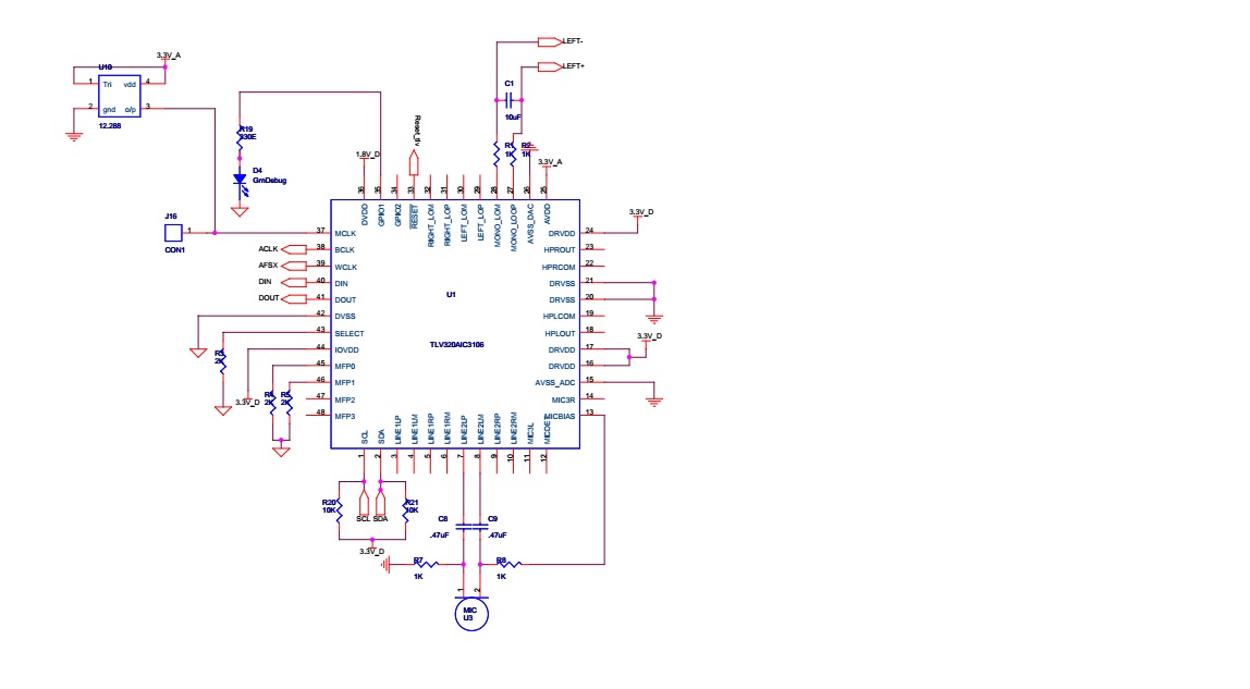
I am trying to read I2S data from TLV320AIC3106 audio codec with a condenser mic connected to left channel.
Below given is my codec settings which is successfully written to the codec that I could read back the registers using I2C.

void tlv320aic3106init(void){
    AudioCodecPageSelect((unsigned char )0x00);
    AudioCodecRegWrite((unsigned char) CODEC_SW_RESET, 0x00);
    // clock generation and control
    AudioCodecRegWrite((unsigned char) CODEC_CLOCK_GENERATION_CONTROL, (unsigned char) 0x02);
    AudioCodecRegWrite((unsigned char) CODEC_ADDITIONAL_GPIO_CONTROL_B, (unsigned char)0x01);  

    AudioCodecRegWrite((unsigned char) CODEC_GPIO1_CONTROL,  0x28);   // clock out on gpio1 pin

    AudioCodecRegWrite((unsigned char) CODEC_SAMPLE_RATE,0XAA);//0xAA);  // fs = fsref/n

    AudioCodecRegWrite((unsigned char) CODEC_MIC_BIAS_CONTROL,   (unsigned char)0xC0);  // MIC bias

    //When selecting an input, unmute the PGAs after routing the input and powering up the ADC.
    AudioCodecRegWrite((unsigned char) CODEC_LINE2L_LEFT_ADC_CONTROL, 0x80);
    AudioCodecRegWrite((unsigned char) CODEC_LINE1L_LEFT_ADC_CONTROL, 0x7C);  // power up left ADC
    AudioCodecRegWrite((unsigned char) CODEC_LEFT_ADC_PGA_GAIN_CONTROL, 0x00); // unmute PGA
}


I am trying to initialise I2S in CPU mode,not DMA mode and read data using ISR.
below is my I2S initialization.

void AudioCaptureRendererConfigure(unsigned char bitsPerSample,
                                    unsigned short bitRate,
                                    unsigned char noOfChannels,
                                    unsigned char RxTx,
                                    unsigned char	dma)
{
 //
    // Initialising the McASP
    //
    MAP_PRCMPeripheralClkEnable(PRCM_I2S,PRCM_RUN_MODE_CLK);
    
    unsigned long	bitClk;

    bitClk = bitsPerSample * bitRate * noOfChannels;
    dma=1;

    if(bitsPerSample == 16)
        {
            MAP_PRCMI2SClockFreqSet(512000); //(bitClk*10));//512000);  (I2S_BASE,(bitClk*10),bitClk,I2S_SLOT_SIZE_16|
            MAP_I2SConfigSetExpClk(I2S_BASE,512000,bitClk,I2S_SLOT_SIZE_16| I2S_PORT_CPU); //(I2S_BASE,512000,bitClk,I2S_SLOT_SIZE_16|
        }


    MAP_I2SIntRegister(I2S_BASE, I2SIntHandler);
    MAP_I2SIntEnable(I2S_BASE,I2S_INT_XDATA);

    if(RxTx == I2S_MODE_RX_TX)
    {
        MAP_I2SSerializerConfig(I2S_BASE,I2S_DATA_LINE_1,I2S_SER_MODE_RX,
                                 I2S_INACT_LOW_LEVEL);
    }

    if(RxTx & I2S_MODE_TX)
    {
        MAP_I2SSerializerConfig(I2S_BASE,I2S_DATA_LINE_0,I2S_SER_MODE_TX,
                                 I2S_INACT_LOW_LEVEL);
    }


}

and the I2Shandler is like below.

void I2SIntHandler(void)
{
unsigned long ulStatus;
unsigned long ulDummy;
// Get the interrupt status
ulStatus = I2SIntStatus(I2S_BASE);
// Check if there was a Transmit interrupt; if so write next data into the tx buffer and acknowledge
// the interrupt
if(ulStatus & I2S_STS_XDATA)
    {
    I2SDataPutNonBlocking(I2S_BASE,I2S_DATA_LINE_0,0xA5);
    I2SIntClear(I2S_BASE,I2S_STS_XDATA);
    I2SIntEnable(I2S_BASE,I2S_INT_XDATA);
    }
// Check if there was a receive interrupt; if so read the data from the rx buffer and acknowledge
// the interrupt
if(ulStatus & I2S_STS_RDATA)
{
    I2SDataGetNonBlocking( I2S_BASE, I2S_DATA_LINE_1,&ulDummy);
    I2SIntClear(I2S_BASE,I2S_STS_RDATA);
    I2SIntEnable(I2S_BASE,I2S_INT_XDATA);
}
}

It is not going into the handler. I put a breakpoint and trying to debug but the control is not getting inside handler.

Is my settings correct?

Thanks & regards,

Vishnu Pradeep

  • Vishnu,

    We are looking into this and will get back to you!

    Thanks,

    Vince Rodriguez
  • Hi,

    This is the connection I am using.

  • Vishnu,

    Are you using TI-RTOS or Free RTOS?
  • Hi Vincent,

    I am not using RTOS as of now. All I am trying to do is reading I2S data out from the audio codec. I can see signals on I2S bitclock, I2S word clock and I2S data line using an oscilloscope. That means initialization of I2S module seems to be okay. Problem may lies with I2S handler initialization and reading data routine. Are my pinmux configuration correct? Is there anything wrong with I2S data line configuration?

     Thanks & regards,

    Vishnu Pradeep

  • Vishnu,

    Please post your PinMuxConfig function in pinmux.c so we could check to see if your pins were configured correctly.

    BR,
    Seong
  • Hi,

    Thanks for the reply. This is the pinmux configuration.

    void
    PinMuxConfig(void)
    {
        //
        // Enable Peripheral Clocks 
        //
        MAP_PRCMPeripheralClkEnable(PRCM_I2S, PRCM_RUN_MODE_CLK);
        MAP_PRCMPeripheralClkEnable(PRCM_UARTA0, PRCM_RUN_MODE_CLK);
        MAP_PRCMPeripheralClkEnable(PRCM_I2CA0, PRCM_RUN_MODE_CLK);
        MAP_PRCMPeripheralClkEnable(PRCM_GPIOA1, PRCM_RUN_MODE_CLK);
        MAP_PRCMPeripheralClkEnable(PRCM_GPIOA2, PRCM_RUN_MODE_CLK);
    
    
           MAP_PRCMPeripheralClkEnable(PRCM_GPIOA0, PRCM_RUN_MODE_CLK);
           MAP_PinTypeGPIO(PIN_60, PIN_MODE_0, false);
           MAP_GPIODirModeSet(GPIOA0_BASE, GPIO_PIN_5, GPIO_DIR_MODE_OUT);


        //
        // Configure PIN_55 for UART0 UART0_TX
        //
        MAP_PinTypeUART(PIN_55, PIN_MODE_3);
    
        //
        // Configure PIN_57 for UART0 UART0_RX
        //
        MAP_PinTypeUART(PIN_57, PIN_MODE_3);
    
        //
        // Configure PIN_64 for MCASP0 D0
        //
        MAP_PinTypeI2S(PIN_64, PIN_MODE_7); //PIN_MODE_7
    
        //
        // Configure PIN_62 for MCASP0 McAFSX CLK
        //
        MAP_PinTypeI2S(PIN_62, PIN_MODE_13);
    
        //
        // Configure PIN_63 for MCASP0 wclk (sync)
    
        //
        MAP_PinTypeI2S(PIN_63, PIN_MODE_7);
    
        //
        // Configure PIN_50 for MCASP0 D1
        //
        MAP_PinTypeI2S(PIN_50, PIN_MODE_6); //PIN_MODE_6
    
        //
        // Configure PIN_01 for I2C0 I2C_SCL
        //
        MAP_PinTypeI2C(PIN_01, PIN_MODE_1);
    
        //
        // Configure PIN_02 for I2C0 I2C_SDA
        //
        MAP_PinTypeI2C(PIN_02, PIN_MODE_1);
    
        //
        // Configure PIN_04 for GPIOInput
        //
        MAP_PinTypeGPIO(PIN_04, PIN_MODE_0, false);
        MAP_GPIODirModeSet(GPIOA1_BASE, 0x20, GPIO_DIR_MODE_IN);
    
        //
        // Configure PIN_15 for GPIOInput
        //
        MAP_PinTypeGPIO(PIN_15, PIN_MODE_0, false);
        MAP_GPIODirModeSet(GPIOA2_BASE, 0x40, GPIO_DIR_MODE_IN);
    
    
        asm(" NOP");
    }

    Thanks & regards,

    vishnu

  • Vishnu,

    Have you tried enabling the RX interrupt by using I2SIntEnable(I2S_BASE,I2S_INT_RDATA); instead of I2SIntEnable(I2S_BASE,I2S_INT_XDATA);

    Also are you calling I2SEnable()?

    Regards,

    Vince Rodriguez
  • Hi Vince,

    Thanks for the response. It was this "I2SIntEnable(I2S_BASE,I2S_INT_RDATA)" function I missed to add. Now the receiving part seems working as it is going to the ISR.

    How can I send data to the slave from CC3200. Can I use I2SDataPut(I2S_BASE, I2S_DATA_LINE_0,0xA0); simply in the main function to check the transmission part working or not?
    How can I make use of the transmit interrupt to send data?

    Thanks & regards,
    Vishnu Pradeep

  • Yes you should be able to send data with that function. I believe the TX interrupt will trigger after you send the data. For more info you can read the I2S section in the TRM:

    www.ti.com/.../swru367c.pdf

    Regards,

    Vince Rodriguez