This thread has been locked.

If you have a related question, please click the "Ask a related question" button in the top right corner. The newly created question will be automatically linked to this question.

WL1831MOD: Experiencing audio quality issue

Part Number: WL1831MOD
Other Parts Discussed in Thread: WL1831

Hello team,

When you get a chance please see below customer question:

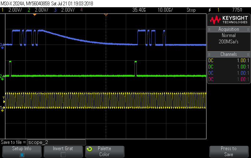
I am working to resolve a poor audio quality issue we are experiencing in our application. I believe I have tracked down the issue to being a sampling rate mismatch between the WL1831MOD wifi/bt transceiver and our WM8281 audio codec.  

I have been reviewing the data sheet available for the WL1831MOD and have discovered that the audio bus (AUD_CLK, AUD_IN, AUD_OUT, FSYNC) being used for transferring audio data to/from the codec can be used in either slave or master mode. Currently is looks to be in master mode with an output sampling rate that is different than what can be selected in the audio codec. Do you have any more reference information on how the master or slave mode is selected and configured? If it's easier to discuss over the phone, please call me

  • Thanks Randhir, if anyone has more knowledge in this area I would love to hear your thoughts.
  • After some more debugging, I have taken a waveform capture of the audio bus to help clarify more of our issue. The interface is I2S where output data from the BT module is the blue waveform, the channel select clock is the green waveform and the main clock is the yellow waveform. Some things I have noted are that the system clock looks fine and measures at 1.024 MHz. The channel clock measures at 16kHz but I would expect the channel select clock to be a 50% duty cycle clock per interface standard but it is clearly not, any ideas why? Lastly the data line has this random exponential decay at the end of some data packets. Almost like that output is not being driven low after the last bit is sent. This could be contributing to our poor audio quality. 

    So to summarize, the data measured is audio from a phone call sent over bluetooth using HFP. Any ideas on why the channel select clock is not a 50% duty cycle waveform and looks the way it does? What could be the reason for the random appearance of signal decay after data packets are sent?


  • codec_8750_general_config.txt
    #select Device Used
    ORCA=0
    TRIO=0
    DIAMOND=1
    
    #select loopback mode, 0-disable, 1-enable
    loopback_enable=0
    
    #select Device Role, 1-Master, 0-Slave
    Master_nSlave=0
    
    ################################  select parameters for on board Codec Configuration	#########################################
    #codec clock as master is configured fixed MCLK/4=3072k (mclk/4=3072, mclk/8=1536, mclk/16=768)
    #codec clock as salve-can be any clock
    #select Codec Role, 1-master, 0-slave  [bits 6]
    codec_master_nslave=1
    
    #codec Fsync can be 8k-0x0c  48k-0x00 96k-0x1c   16k - 0x14
    codec_Fsync=0x14
    
    #pcm_clock = 3072 then
    #select data width, 0=16bit, 1=20bit, 2=24bit, 3=32bit [bits 3:2]
    data_width=0
    
    #select data offset, 1=offset 0,MSB on 1nd bit	0-offset 1, MSB on 2nd clock [bits 4]
    noffset=0
    
    #select I2S/PCM mode, 3 - PCM mode (DSP mode), 2-I2S mode 
    format=3
     
    if (codec_Fsync==0x0c)then
    device_fSync=8000
    elseif (codec_Fsync==0x00) then
    device_fSync=48000
    elseif (codec_Fsync==0x1c) then
    device_fSync=96000
    elseif (codec_Fsync==0x14) then
    device_fSync=16000
    endif
    
    
    format_hex=format &0x3
    noffset_hex=noffset<<4
    codec_master_nslave_reg=codec_master_nslave<<6
    data_width_hex=(data_width & 0x3)<<3
    codec_config=data_width_hex|codec_master_nslave_reg|noffset_hex|format_hex
    
    
    ############################### end of on board codec configuration	###############################################
    
    ############################### Config Device PCM parameters		###############################################
    
    if (Master_nSlave) then
    	Send_HCI_VS_Write_CODEC_Config 0xFD06, 3072, 0x00, device_fSync, 0x0001, 1, 0x00, 0x00, 16, 0x0001, 1, 16, 0x0001, 0, 0x00, 16, 17, 0x01, 16, 17, 0x00, 0x00
    	Wait_HCI_Command_Complete_VS_Write_CODEC_Config_Event 5000, any, HCI_VS_Write_CODEC_Config, 0x00
    else
    	Send_HCI_VS_Write_CODEC_Config 0xFD06, 3072, 0x01, device_fSync, 0x0001, 0, 0x00, 0x00, 0x0010, 0x0001, 1, 0x0010, 0x0001, 0, 0x00, 0x0010, 0x0011, 0x01, 0x0010, 0x0011, 0x00, 0x00
    	Wait_HCI_Command_Complete_VS_Write_CODEC_Config_Event 5000, any, HCI_VS_Write_CODEC_Config, 0x00
    end if
    
    # TEMP - change Dout mode to "always output"
    Send_HCI_VS_Write_CODEC_Config_Enhanced 0xFD07, 0x00, 0x0000, 0x0000, 0x00, 0x04, 0x04, 0x01, 0x00, 0x000000, 0x00, 0x00, 0x04, 0x04, 0x01, 0x00, 0x000000, 0x00, 0x00
    Wait_HCI_Command_Complete_VS_Write_CODEC_Config_Enhanced_Event 5000, any, HCI_VS_Write_CODEC_Config_Enhanced, 0x00
    ######################################################################################################################
    
    
    ##########################	Mux I2C bus for codec configuration	###################################################
    if ORCA then
    	Send_HCI_VS_Write_Hardware_Register 0xFF01, 0x001A7c9c, 0x1600
    	Wait_HCI_Command_Complete_VS_Write_Hardware_Register_Event 5000, any, HCI_VS_Write_Hardware_Register, 0x00
    	Send_HCI_VS_Read_Modify_Write_Hardware_Register 0xFD09, 0x001A7cac, 0x0010, 0x0010
    	Wait_HCI_Command_Complete_VS_Read_Modify_Write_Hardware_Register_Event 5000, any, HCI_VS_Read_Modify_Write_Hardware_Register, 0x00
    
    	#Send_Set_IO_Pin_Mux_BTIP 0x10, 0x06
    	#Send_Set_IO_Pin_Mux_BTIP 0x0f, 0x06
    	Send_HCI_VS_Read_Modify_Write_Hardware_Register 0xFD09, 0x001Af616, 0x6600, 0xff00
    	Wait_HCI_Command_Complete_VS_Read_Modify_Write_Hardware_Register_Event 5000, any, HCI_VS_Read_Modify_Write_Hardware_Register, 0x00
    
    	#Send_Set_IO_Pin_Mux_Orca_top 0x11, 0x04		
    	#Send_Set_IO_Pin_Mux_Orca_top 0x12, 0x04
    	#read value for restore
    	Send_HCI_VS_Read_Hardware_Register 0xFF00, 0x001A7c96
    	Wait_HCI_Command_Complete_VS_Read_Hardware_Register_Event 5000, any, HCI_VS_Read_Hardware_Register, 0x00, &ORCA_TOP_I2C
    	
    	Send_HCI_VS_Read_Modify_Write_Hardware_Register 0xFD09, 0x001A7c96, 0x0404, 0x0f0f
    	Wait_HCI_Command_Complete_VS_Read_Modify_Write_Hardware_Register_Event 5000, any, HCI_VS_Read_Modify_Write_Hardware_Register, 0x00
    
    	#allowe I2C both on FM and Codec
    	Send_HCI_VS_Read_Modify_Write_Hardware_Register 0xFD09, 0x001a400c, 0x0001, 0x0003
    	Wait_HCI_Command_Complete_VS_Read_Modify_Write_Hardware_Register_Event 5000, any, HCI_VS_Read_Modify_Write_Hardware_Register, 0x00
    endif
    
    if TRIO then
    	Send_HCI_VS_Read_Hardware_Register 0xFF00, 0x1a7c8c
    	Wait_HCI_Command_Complete_VS_Read_Hardware_Register_Event 5000, any, HCI_VS_Read_Hardware_Register, 0x00, &TRIO_I2C_TOP
    	#select bt_func6,7 on top
    	Send_HCI_VS_Write_Hardware_Register 0xFF01, 0x1a7c8c, 0x0000
    	Wait_HCI_Command_Complete_VS_Write_Hardware_Register_Event 5000, any, HCI_VS_Write_Hardware_Register, 0x00
    	#Send_Set_IO_Pin_Mux_BTIP 0x10, 0x06
    	#Send_Set_IO_Pin_Mux_BTIP 0x0f, 0x06
    	Send_HCI_VS_Read_Modify_Write_Hardware_Register 0xFD09, 0x001Af616, 0x6600, 0xff00
    	Wait_HCI_Command_Complete_VS_Read_Modify_Write_Hardware_Register_Event 5000, any, HCI_VS_Read_Modify_Write_Hardware_Register, 0x00
    
    endif
    
    if DIAMOND then
    	# Read BT_FUNC6_SEL
    	Send_HCI_VS_Read_Hardware_Register 0xFF00, 0x200ce122
    	Wait_HCI_Command_Complete_VS_Read_Hardware_Register_Event 5000, any, HCI_VS_Read_Hardware_Register, 0x00, &I2C_BTFUNC6_18xx
    	# Read BT_FUNC7_SEL
    	Send_HCI_VS_Read_Hardware_Register 0xFF00, 0x200ce124
    	Wait_HCI_Command_Complete_VS_Read_Hardware_Register_Event 5000, any, HCI_VS_Read_Hardware_Register, 0x00, &I2C_BTFUNC7_18xx
    	#select bt_func6 on bt_func6
    	Send_HCI_VS_Read_Modify_Write_Hardware_Register 0xFD09, 0x200ce122, 0x0000, 0x001f
    	Wait_HCI_Command_Complete_VS_Read_Modify_Write_Hardware_Register_Event 5000, any, HCI_VS_Read_Modify_Write_Hardware_Register, 0x00
    	#select bt_func7 on bt_func7
    	Send_HCI_VS_Read_Modify_Write_Hardware_Register 0xFD09, 0x200ce124, 0x0000, 0x001f
    	Wait_HCI_Command_Complete_VS_Read_Modify_Write_Hardware_Register_Event 5000, any, HCI_VS_Read_Modify_Write_Hardware_Register, 0x00
    	
    	# btfanc 6 --> sda &  btfanc 7 --> scl
    	Send_HCI_VS_Write_Hardware_Register 0xFF01, 0x200Ef516, 0x6600
    	Wait_HCI_Command_Complete_VS_Write_Hardware_Register_Event 5000, any, HCI_VS_Write_Hardware_Register, 0x00
    #	Send_Set_IO_Pin_Mux_BTIP 0x0f, 0x06	
    #	Send_Set_IO_Pin_Mux_BTIP 0x10, 0x06
    endif
    
    #################################	end I2C mux configuration	#############################################################


    #################################  This script is for WM8750 codec  #################################################################
    
    #CODEC ID = 0x1a
    #CODEC Register address=HEX{[I2C Sub Address]/2}
    
    # reset codec
    Send_HCI_VS_Write_I2C_Register_Enhanced 0xFD36, 0x1a, 0, 100, 0x01, 0x1e, 0x01, "00"
    Wait_HCI_Command_Complete_VS_Write_I2C_Register_Enhanced_Event 5000, any, HCI_VS_Write_I2C_Register_Enhanced, 0x00
          
    # set device power management 
    Send_HCI_VS_Write_I2C_Register_Enhanced 0xFD36, 0x1a, 0, 100, 0x01, 0x32, 0x01, "FE"
    Wait_HCI_Command_Complete_VS_Write_I2C_Register_Enhanced_Event 5000, any, HCI_VS_Write_I2C_Register_Enhanced, 0x00


    # Enable All Analog inputs and outputs
    # DACL =  (bit8) 
    # DACR =  (bit7) 
    # Lout1 = (bit6)
    # Rout1 = (bit5)
    # Lout2 = (bit4)
    # Rout2 = (bit3)
    Send_HCI_VS_Write_I2C_Register_Enhanced 0xFD36, 0x1a, 0, 100, 0x01, 0x35, 0x01, "FE"
    Wait_HCI_Command_Complete_VS_Write_I2C_Register_Enhanced_Event 5000, any, HCI_VS_Write_I2C_Register_Enhanced, 0x00


    # set left line input (codec address = 0x00) vol = default, un-mute , bit 8 - update now (LIVU)
    Send_HCI_VS_Write_I2C_Register_Enhanced 0xFD36, 0x1a, 0, 100, 0x01, 0x01, 0x01, "17"
    Wait_HCI_Command_Complete_VS_Write_I2C_Register_Enhanced_Event 5000, any, HCI_VS_Write_I2C_Register_Enhanced, 0x00
    
          
    # set right line input (address = 0x02) vol = default, un-mute , update now (RIVU)
    Send_HCI_VS_Write_I2C_Register_Enhanced 0xFD36, 0x1a, 0, 100, 0x01, 0x03, 0x01, "17"
    Wait_HCI_Command_Complete_VS_Write_I2C_Register_Enhanced_Event 5000, any, HCI_VS_Write_I2C_Register_Enhanced, 0x00
    #Wait_HCI_Command_Complete_VS_Write_I2C_Register_Event 5000, any, 0xFE0E, 0x00
    
    # digital path - unmute the DAC (bit4=0)
    Send_HCI_VS_Write_I2C_Register_Enhanced 0xFD36, 0x1a, 0, 100, 0x01, 0x0a, 0x01, "00"
    Wait_HCI_Command_Complete_VS_Write_I2C_Register_Enhanced_Event 5000, any, HCI_VS_Write_I2C_Register_Enhanced, 0x00
    
    
    #set codec left input to input2 , LINSEL=01 (bits 7:6)- sutable for 18xx HDMB and ORCA/TRIO MB
    Send_HCI_VS_Write_I2C_Register_Enhanced 0xFD36, 0x1a, 0, 100, 0x01, 0x40, 0x01, "40"
    Wait_HCI_Command_Complete_VS_Write_I2C_Register_Enhanced_Event 5000, any, HCI_VS_Write_I2C_Register_Enhanced, 0x00
    
    #set codec right input to input2 , RINSEL=01 (bits 7:6)- sutable for 18xx HDMB and ORCA/TRIO MB
    Send_HCI_VS_Write_I2C_Register_Enhanced 0xFD36, 0x1a, 0, 100, 0x01, 0x42, 0x01, "40"
    Wait_HCI_Command_Complete_VS_Write_I2C_Register_Enhanced_Event 5000, any, HCI_VS_Write_I2C_Register_Enhanced, 0x00
    
    #set left ADC to output (enable left dac to left mixer), left mixer volume set, bits 6:4, set to 0x1
    Send_HCI_VS_Write_I2C_Register_Enhanced 0xFD36, 0x1a, 0, 100, 0x01, 0x45, 0x01, "50"
    Wait_HCI_Command_Complete_VS_Write_I2C_Register_Enhanced_Event 5000, any, HCI_VS_Write_I2C_Register_Enhanced, 0x00
    
    #set right ADC to output (enable right dac to right mixer)   
    Send_HCI_VS_Write_I2C_Register_Enhanced 0xFD36, 0x1a, 0, 100, 0x01, 0x4b, 0x01, "50"
    Wait_HCI_Command_Complete_VS_Write_I2C_Register_Enhanced_Event 5000, any, HCI_VS_Write_I2C_Register_Enhanced, 0x00
    #Wait_HCI_Command_Complete_VS_Write_I2C_Register_Event 5000, any, 0xFE0E, 0x00
    
       
    # Digital Interface Activation-clocking & sample rate 8k-0x0c  48k-0x00 96k-0x1c   16k - 0x14
    Send_HCI_VS_Write_I2C_Register_Enhanced 0xFD36, 0x1a, 0, 100, 0x01, 0x10, 0x01, codec_Fsync
    Wait_HCI_Command_Complete_VS_Write_I2C_Register_Enhanced_Event 5000, any, HCI_VS_Write_I2C_Register_Enhanced, 0x00
    
    
    # PCM, MSB on 2nd bit, codec master=43   *
    # PCM, MSB on 2nd bit, codec slave=03    *
    # PCM, MSB on 1nd bit, codec master=53   
    # PCM, MSB on 1nd bit, codec slave=13    
    # I2S, MSB on 2nd clock, codec master=42 *
    # I2S, MSB on 2nd clock, codec slave=02  *
    Send_HCI_VS_Write_I2C_Register_Enhanced 0xFD36, 0x1a, 0, 100, 0x01, 0x0E, 0x01, codec_config
    Wait_HCI_Command_Complete_VS_Write_I2C_Register_Enhanced_Event 5000, any, HCI_VS_Write_I2C_Register_Enhanced, 0x00
    
    
    #######################################	End of codec configuration WM8750	##########################################
    
    #######################################	Restore I2C pads to their original function	##################################
    #for DIAMOND
    if DIAMOND then
    	#restore bt_func6 top func
    	Send_HCI_VS_Read_Modify_Write_Hardware_Register 0xFD09, 0x200ce122, I2C_BTFUNC6_18xx, 0xffff
    	Wait_HCI_Command_Complete_VS_Read_Modify_Write_Hardware_Register_Event 5000, any, HCI_VS_Read_Modify_Write_Hardware_Register, 0x00
    	#restore bt_func7 top func
    	Send_HCI_VS_Read_Modify_Write_Hardware_Register 0xFD09, 0x200ce124, I2C_BTFUNC7_18xx, 0xffff
    	Wait_HCI_Command_Complete_VS_Read_Modify_Write_Hardware_Register_Event 5000, any, HCI_VS_Read_Modify_Write_Hardware_Register, 0x00
    endif
    if ORCA then
    	#restore FM_SCL/FM_SDA top func
    	Send_HCI_VS_Read_Modify_Write_Hardware_Register 0xFD09, 0x001A7c96, ORCA_TOP_I2C, 0xffff
    	Wait_HCI_Command_Complete_VS_Read_Modify_Write_Hardware_Register_Event 5000, any, HCI_VS_Read_Modify_Write_Hardware_Register, 0x00
    endif
    if TRIO then
    	#restore bt_func6,7 on top
    	Send_HCI_VS_Write_Hardware_Register 0xFF01, 0x1a7c8c, TRIO_I2C_TOP
    	Wait_HCI_Command_Complete_VS_Write_Hardware_Register_Event 5000, any, HCI_VS_Write_Hardware_Register, 0x00
    endif
    ################################	end of pinmux restore	#########################################
    
    ################################	loopback mode	#################################################
    
    Send_HCI_VS_Set_Pcm_Loopback_Enable 0xFE28, 1
    Wait_HCI_Command_Complete_VS_Set_Pcm_Loopback_Enable_Event 5000, any, HCI_VS_Set_Pcm_Loopback_Enable, 0x00
    
    Exit
    
    
    Send_HCI_VS_Set_Pcm_Loopback_Enable 0xFE28, 0
    Send_HCI_VS_Set_Pcm_Loopback_Enable 0xFE28, 1
    Hello Randhir S Kalsi,

    Can you please add the exact configuration you have done to the CODEC (HCI Command you send).

    I'm attaching here a file as an example.

    BR,

    Chen Loewy

  • 7242.codec_8750_general_config.txt
    #select Device Used
    ORCA=0
    TRIO=0
    DIAMOND=1
    
    #select loopback mode, 0-disable, 1-enable
    loopback_enable=0
    
    #select Device Role, 1-Master, 0-Slave
    Master_nSlave=0
    
    ################################  select parameters for on board Codec Configuration	#########################################
    #codec clock as master is configured fixed MCLK/4=3072k (mclk/4=3072, mclk/8=1536, mclk/16=768)
    #codec clock as salve-can be any clock
    #select Codec Role, 1-master, 0-slave  [bits 6]
    codec_master_nslave=1
    
    #codec Fsync can be 8k-0x0c  48k-0x00 96k-0x1c   16k - 0x14
    codec_Fsync=0x14
    
    #pcm_clock = 3072 then
    #select data width, 0=16bit, 1=20bit, 2=24bit, 3=32bit [bits 3:2]
    data_width=0
    
    #select data offset, 1=offset 0,MSB on 1nd bit	0-offset 1, MSB on 2nd clock [bits 4]
    noffset=0
    
    #select I2S/PCM mode, 3 - PCM mode (DSP mode), 2-I2S mode 
    format=3
     
    if (codec_Fsync==0x0c)then
    device_fSync=8000
    elseif (codec_Fsync==0x00) then
    device_fSync=48000
    elseif (codec_Fsync==0x1c) then
    device_fSync=96000
    elseif (codec_Fsync==0x14) then
    device_fSync=16000
    endif
    
    
    format_hex=format &0x3
    noffset_hex=noffset<<4
    codec_master_nslave_reg=codec_master_nslave<<6
    data_width_hex=(data_width & 0x3)<<3
    codec_config=data_width_hex|codec_master_nslave_reg|noffset_hex|format_hex
    
    
    ############################### end of on board codec configuration	###############################################
    
    ############################### Config Device PCM parameters		###############################################
    
    if (Master_nSlave) then
    	Send_HCI_VS_Write_CODEC_Config 0xFD06, 3072, 0x00, device_fSync, 0x0001, 1, 0x00, 0x00, 16, 0x0001, 1, 16, 0x0001, 0, 0x00, 16, 17, 0x01, 16, 17, 0x00, 0x00
    	Wait_HCI_Command_Complete_VS_Write_CODEC_Config_Event 5000, any, HCI_VS_Write_CODEC_Config, 0x00
    else
    	Send_HCI_VS_Write_CODEC_Config 0xFD06, 3072, 0x01, device_fSync, 0x0001, 0, 0x00, 0x00, 0x0010, 0x0001, 1, 0x0010, 0x0001, 0, 0x00, 0x0010, 0x0011, 0x01, 0x0010, 0x0011, 0x00, 0x00
    	Wait_HCI_Command_Complete_VS_Write_CODEC_Config_Event 5000, any, HCI_VS_Write_CODEC_Config, 0x00
    end if
    
    # TEMP - change Dout mode to "always output"
    Send_HCI_VS_Write_CODEC_Config_Enhanced 0xFD07, 0x00, 0x0000, 0x0000, 0x00, 0x04, 0x04, 0x01, 0x00, 0x000000, 0x00, 0x00, 0x04, 0x04, 0x01, 0x00, 0x000000, 0x00, 0x00
    Wait_HCI_Command_Complete_VS_Write_CODEC_Config_Enhanced_Event 5000, any, HCI_VS_Write_CODEC_Config_Enhanced, 0x00
    ######################################################################################################################
    
    
    ##########################	Mux I2C bus for codec configuration	###################################################
    if ORCA then
    	Send_HCI_VS_Write_Hardware_Register 0xFF01, 0x001A7c9c, 0x1600
    	Wait_HCI_Command_Complete_VS_Write_Hardware_Register_Event 5000, any, HCI_VS_Write_Hardware_Register, 0x00
    	Send_HCI_VS_Read_Modify_Write_Hardware_Register 0xFD09, 0x001A7cac, 0x0010, 0x0010
    	Wait_HCI_Command_Complete_VS_Read_Modify_Write_Hardware_Register_Event 5000, any, HCI_VS_Read_Modify_Write_Hardware_Register, 0x00
    
    	#Send_Set_IO_Pin_Mux_BTIP 0x10, 0x06
    	#Send_Set_IO_Pin_Mux_BTIP 0x0f, 0x06
    	Send_HCI_VS_Read_Modify_Write_Hardware_Register 0xFD09, 0x001Af616, 0x6600, 0xff00
    	Wait_HCI_Command_Complete_VS_Read_Modify_Write_Hardware_Register_Event 5000, any, HCI_VS_Read_Modify_Write_Hardware_Register, 0x00
    
    	#Send_Set_IO_Pin_Mux_Orca_top 0x11, 0x04		
    	#Send_Set_IO_Pin_Mux_Orca_top 0x12, 0x04
    	#read value for restore
    	Send_HCI_VS_Read_Hardware_Register 0xFF00, 0x001A7c96
    	Wait_HCI_Command_Complete_VS_Read_Hardware_Register_Event 5000, any, HCI_VS_Read_Hardware_Register, 0x00, &ORCA_TOP_I2C
    	
    	Send_HCI_VS_Read_Modify_Write_Hardware_Register 0xFD09, 0x001A7c96, 0x0404, 0x0f0f
    	Wait_HCI_Command_Complete_VS_Read_Modify_Write_Hardware_Register_Event 5000, any, HCI_VS_Read_Modify_Write_Hardware_Register, 0x00
    
    	#allowe I2C both on FM and Codec
    	Send_HCI_VS_Read_Modify_Write_Hardware_Register 0xFD09, 0x001a400c, 0x0001, 0x0003
    	Wait_HCI_Command_Complete_VS_Read_Modify_Write_Hardware_Register_Event 5000, any, HCI_VS_Read_Modify_Write_Hardware_Register, 0x00
    endif
    
    if TRIO then
    	Send_HCI_VS_Read_Hardware_Register 0xFF00, 0x1a7c8c
    	Wait_HCI_Command_Complete_VS_Read_Hardware_Register_Event 5000, any, HCI_VS_Read_Hardware_Register, 0x00, &TRIO_I2C_TOP
    	#select bt_func6,7 on top
    	Send_HCI_VS_Write_Hardware_Register 0xFF01, 0x1a7c8c, 0x0000
    	Wait_HCI_Command_Complete_VS_Write_Hardware_Register_Event 5000, any, HCI_VS_Write_Hardware_Register, 0x00
    	#Send_Set_IO_Pin_Mux_BTIP 0x10, 0x06
    	#Send_Set_IO_Pin_Mux_BTIP 0x0f, 0x06
    	Send_HCI_VS_Read_Modify_Write_Hardware_Register 0xFD09, 0x001Af616, 0x6600, 0xff00
    	Wait_HCI_Command_Complete_VS_Read_Modify_Write_Hardware_Register_Event 5000, any, HCI_VS_Read_Modify_Write_Hardware_Register, 0x00
    
    endif
    
    if DIAMOND then
    	# Read BT_FUNC6_SEL
    	Send_HCI_VS_Read_Hardware_Register 0xFF00, 0x200ce122
    	Wait_HCI_Command_Complete_VS_Read_Hardware_Register_Event 5000, any, HCI_VS_Read_Hardware_Register, 0x00, &I2C_BTFUNC6_18xx
    	# Read BT_FUNC7_SEL
    	Send_HCI_VS_Read_Hardware_Register 0xFF00, 0x200ce124
    	Wait_HCI_Command_Complete_VS_Read_Hardware_Register_Event 5000, any, HCI_VS_Read_Hardware_Register, 0x00, &I2C_BTFUNC7_18xx
    	#select bt_func6 on bt_func6
    	Send_HCI_VS_Read_Modify_Write_Hardware_Register 0xFD09, 0x200ce122, 0x0000, 0x001f
    	Wait_HCI_Command_Complete_VS_Read_Modify_Write_Hardware_Register_Event 5000, any, HCI_VS_Read_Modify_Write_Hardware_Register, 0x00
    	#select bt_func7 on bt_func7
    	Send_HCI_VS_Read_Modify_Write_Hardware_Register 0xFD09, 0x200ce124, 0x0000, 0x001f
    	Wait_HCI_Command_Complete_VS_Read_Modify_Write_Hardware_Register_Event 5000, any, HCI_VS_Read_Modify_Write_Hardware_Register, 0x00
    	
    	# btfanc 6 --> sda &  btfanc 7 --> scl
    	Send_HCI_VS_Write_Hardware_Register 0xFF01, 0x200Ef516, 0x6600
    	Wait_HCI_Command_Complete_VS_Write_Hardware_Register_Event 5000, any, HCI_VS_Write_Hardware_Register, 0x00
    #	Send_Set_IO_Pin_Mux_BTIP 0x0f, 0x06	
    #	Send_Set_IO_Pin_Mux_BTIP 0x10, 0x06
    endif
    
    #################################	end I2C mux configuration	#############################################################


    #################################  This script is for WM8750 codec  #################################################################
    
    #CODEC ID = 0x1a
    #CODEC Register address=HEX{[I2C Sub Address]/2}
    
    # reset codec
    Send_HCI_VS_Write_I2C_Register_Enhanced 0xFD36, 0x1a, 0, 100, 0x01, 0x1e, 0x01, "00"
    Wait_HCI_Command_Complete_VS_Write_I2C_Register_Enhanced_Event 5000, any, HCI_VS_Write_I2C_Register_Enhanced, 0x00
          
    # set device power management 
    Send_HCI_VS_Write_I2C_Register_Enhanced 0xFD36, 0x1a, 0, 100, 0x01, 0x32, 0x01, "FE"
    Wait_HCI_Command_Complete_VS_Write_I2C_Register_Enhanced_Event 5000, any, HCI_VS_Write_I2C_Register_Enhanced, 0x00


    # Enable All Analog inputs and outputs
    # DACL =  (bit8) 
    # DACR =  (bit7) 
    # Lout1 = (bit6)
    # Rout1 = (bit5)
    # Lout2 = (bit4)
    # Rout2 = (bit3)
    Send_HCI_VS_Write_I2C_Register_Enhanced 0xFD36, 0x1a, 0, 100, 0x01, 0x35, 0x01, "FE"
    Wait_HCI_Command_Complete_VS_Write_I2C_Register_Enhanced_Event 5000, any, HCI_VS_Write_I2C_Register_Enhanced, 0x00


    # set left line input (codec address = 0x00) vol = default, un-mute , bit 8 - update now (LIVU)
    Send_HCI_VS_Write_I2C_Register_Enhanced 0xFD36, 0x1a, 0, 100, 0x01, 0x01, 0x01, "17"
    Wait_HCI_Command_Complete_VS_Write_I2C_Register_Enhanced_Event 5000, any, HCI_VS_Write_I2C_Register_Enhanced, 0x00
    
          
    # set right line input (address = 0x02) vol = default, un-mute , update now (RIVU)
    Send_HCI_VS_Write_I2C_Register_Enhanced 0xFD36, 0x1a, 0, 100, 0x01, 0x03, 0x01, "17"
    Wait_HCI_Command_Complete_VS_Write_I2C_Register_Enhanced_Event 5000, any, HCI_VS_Write_I2C_Register_Enhanced, 0x00
    #Wait_HCI_Command_Complete_VS_Write_I2C_Register_Event 5000, any, 0xFE0E, 0x00
    
    # digital path - unmute the DAC (bit4=0)
    Send_HCI_VS_Write_I2C_Register_Enhanced 0xFD36, 0x1a, 0, 100, 0x01, 0x0a, 0x01, "00"
    Wait_HCI_Command_Complete_VS_Write_I2C_Register_Enhanced_Event 5000, any, HCI_VS_Write_I2C_Register_Enhanced, 0x00
    
    
    #set codec left input to input2 , LINSEL=01 (bits 7:6)- sutable for 18xx HDMB and ORCA/TRIO MB
    Send_HCI_VS_Write_I2C_Register_Enhanced 0xFD36, 0x1a, 0, 100, 0x01, 0x40, 0x01, "40"
    Wait_HCI_Command_Complete_VS_Write_I2C_Register_Enhanced_Event 5000, any, HCI_VS_Write_I2C_Register_Enhanced, 0x00
    
    #set codec right input to input2 , RINSEL=01 (bits 7:6)- sutable for 18xx HDMB and ORCA/TRIO MB
    Send_HCI_VS_Write_I2C_Register_Enhanced 0xFD36, 0x1a, 0, 100, 0x01, 0x42, 0x01, "40"
    Wait_HCI_Command_Complete_VS_Write_I2C_Register_Enhanced_Event 5000, any, HCI_VS_Write_I2C_Register_Enhanced, 0x00
    
    #set left ADC to output (enable left dac to left mixer), left mixer volume set, bits 6:4, set to 0x1
    Send_HCI_VS_Write_I2C_Register_Enhanced 0xFD36, 0x1a, 0, 100, 0x01, 0x45, 0x01, "50"
    Wait_HCI_Command_Complete_VS_Write_I2C_Register_Enhanced_Event 5000, any, HCI_VS_Write_I2C_Register_Enhanced, 0x00
    
    #set right ADC to output (enable right dac to right mixer)   
    Send_HCI_VS_Write_I2C_Register_Enhanced 0xFD36, 0x1a, 0, 100, 0x01, 0x4b, 0x01, "50"
    Wait_HCI_Command_Complete_VS_Write_I2C_Register_Enhanced_Event 5000, any, HCI_VS_Write_I2C_Register_Enhanced, 0x00
    #Wait_HCI_Command_Complete_VS_Write_I2C_Register_Event 5000, any, 0xFE0E, 0x00
    
       
    # Digital Interface Activation-clocking & sample rate 8k-0x0c  48k-0x00 96k-0x1c   16k - 0x14
    Send_HCI_VS_Write_I2C_Register_Enhanced 0xFD36, 0x1a, 0, 100, 0x01, 0x10, 0x01, codec_Fsync
    Wait_HCI_Command_Complete_VS_Write_I2C_Register_Enhanced_Event 5000, any, HCI_VS_Write_I2C_Register_Enhanced, 0x00
    
    
    # PCM, MSB on 2nd bit, codec master=43   *
    # PCM, MSB on 2nd bit, codec slave=03    *
    # PCM, MSB on 1nd bit, codec master=53   
    # PCM, MSB on 1nd bit, codec slave=13    
    # I2S, MSB on 2nd clock, codec master=42 *
    # I2S, MSB on 2nd clock, codec slave=02  *
    Send_HCI_VS_Write_I2C_Register_Enhanced 0xFD36, 0x1a, 0, 100, 0x01, 0x0E, 0x01, codec_config
    Wait_HCI_Command_Complete_VS_Write_I2C_Register_Enhanced_Event 5000, any, HCI_VS_Write_I2C_Register_Enhanced, 0x00
    
    
    #######################################	End of codec configuration WM8750	##########################################
    
    #######################################	Restore I2C pads to their original function	##################################
    #for DIAMOND
    if DIAMOND then
    	#restore bt_func6 top func
    	Send_HCI_VS_Read_Modify_Write_Hardware_Register 0xFD09, 0x200ce122, I2C_BTFUNC6_18xx, 0xffff
    	Wait_HCI_Command_Complete_VS_Read_Modify_Write_Hardware_Register_Event 5000, any, HCI_VS_Read_Modify_Write_Hardware_Register, 0x00
    	#restore bt_func7 top func
    	Send_HCI_VS_Read_Modify_Write_Hardware_Register 0xFD09, 0x200ce124, I2C_BTFUNC7_18xx, 0xffff
    	Wait_HCI_Command_Complete_VS_Read_Modify_Write_Hardware_Register_Event 5000, any, HCI_VS_Read_Modify_Write_Hardware_Register, 0x00
    endif
    if ORCA then
    	#restore FM_SCL/FM_SDA top func
    	Send_HCI_VS_Read_Modify_Write_Hardware_Register 0xFD09, 0x001A7c96, ORCA_TOP_I2C, 0xffff
    	Wait_HCI_Command_Complete_VS_Read_Modify_Write_Hardware_Register_Event 5000, any, HCI_VS_Read_Modify_Write_Hardware_Register, 0x00
    endif
    if TRIO then
    	#restore bt_func6,7 on top
    	Send_HCI_VS_Write_Hardware_Register 0xFF01, 0x1a7c8c, TRIO_I2C_TOP
    	Wait_HCI_Command_Complete_VS_Write_Hardware_Register_Event 5000, any, HCI_VS_Write_Hardware_Register, 0x00
    endif
    ################################	end of pinmux restore	#########################################
    
    ################################	loopback mode	#################################################
    
    Send_HCI_VS_Set_Pcm_Loopback_Enable 0xFE28, loopback_enable
    Wait_HCI_Command_Complete_VS_Set_Pcm_Loopback_Enable_Event 5000, any, HCI_VS_Set_Pcm_Loopback_Enable, 0x00
    
    Exit


    Hi Westin,

    I've attached the wrong file.

    please try the following please.

    BR,

    Chen Loewy

  • Hi Chen,

    this project is something my company has inherited and we are currently reverse engineering the product to fix issues. I haven't been able to locate a config file for this part yet. Do you know of any key information specific to the WL1831 I could use as a search term to find the config file? Also, is there additional documentation for this part regarding registers settings? I haven't found any additional documentation besides the datasheet that doesn't have this information. Thanks

  • Hi Westin,

    Can you please send me the .bts file you are using?
    sometimes these configurations are part of it.

    I will go over it and check.

    Chen
  • I attached a folder containing 4 .bts files I found in our current software. I'm not sure which one one is of interest but I could not read those files to verify what was in them. Let me know if that is or isn't what you needed.

    One additional question, I have gone so far as to use a logic analyzer to record the pcm data coming out of the wl1831 before the codec and then decoded it to a .wav file for comparing with audio coming out of the codec, however, the data does not look like typical 16-bit quantization. Is there a different encoding scheme used for the i2s/pcm audio bus on the wl1831? Thanks

    bts files.tar.gz

  • Hello, I am still having audio quality issues. After measuring the data and clock signals coming out of the i2s bus using a logic analyzer, I was able to decode the data and listen to the audio. The issue remains after using default decode settings, (16bit word sizes, 16kHz sampling, 2's complement data, etc.) I found a config file after digging through our repo named wl18xx-conf.bin (.bin files restricted from uploading); is it something that would have been produced by TI? Thanks

  • Hello Westin,

    I went over the .bts files you've sent me.

    out of the 4 only one makes sense (which is a WL8 one).

    Having said that - there is no codec configuration in this file.

    The file you've mentioned .conf - is a WiFi file and not a Bluetooth file.

    You need to find the file where you configure the codec or try using the file i have sent you and check if it works well using it.

    BR,

    Chen Loewy

  • Hi Chen, 

    I think I have discovered how/where they are sending HCI commands and the audio config settings to the WL1831. I found out those settings are referenced by the register address 0XFD06. I have copied the config parameters below. I haven't fully narrowed down how this function is called or operates but those two config arrays should be the setting for that register address. I found the HCI command list online but am having trouble decoding those arrays to there corresponding settings. Does this look correct and would you be able to decode what these two profiles mean?

    static void configure_chip()
    {
    uint8_t param_ti_nb_config[] = {0x00,0x02,0x00,0x40,0x1F,0x00,0x00,0x01,0x00,0x00,0x00,0x00,0x10, 0x00, 0x01, 0x00, 0x01, 0x10, 0x00, 0x01, 0x00, 0x00, 0x00, 0x10, 0x00, 0x11, 0x00, 0x01, 0x10, 0x00, 0x11, 0x00, 0x00, 0x00};
    uint8_t param_ti_wb_config[] = {0x00,0x04,0x00,0x80,0x3E,0x00,0x00,0x01,0x00,0x00,0x00,0x00,0x10, 0x00, 0x01, 0x00, 0x01, 0x10, 0x00, 0x01, 0x00, 0x00, 0x00, 0x10, 0x00, 0x11, 0x00, 0x01, 0x10, 0x00, 0x11, 0x00, 0x00, 0x00};


    uint16_t opcode_codec_config;

    opcode_codec_config = 0xFD06;

    BTM_VendorSpecificCommand(opcode_codec_config,sizeof(param_ti_nb_config),param_ti_nb_config,NULL);
    }
  • Also, is there a more up-to-date version of this HCI Command list. I have found 3 typos in the audio section alone.

    swru442b.pdf

  • Hello again,

    I am back trying to discover our audio issue with the WL1831. I have configured the audio PCM channel correctly and it has not improved the poor audio quality we are experiencing. 

    As a test, I decoded a single tone (440 Hz) playing over HFP and have discovered that the WL1831 PCM output channel is latching to values for a random amount of time. I am not sure what could be the cause of such an issue. Do you have any ideas? Thanks  

  • Hi Westin,

    The decoded signal above looks like it the "latching" might be happening due to packet loss. Could you please capture the Bluetooth Firmware logs (User's Guide) of the WL183x when running this test?

    Best regards,

    Vihang

  • Hi Vihang,

    I have done some additional testing in debug mode with the BT module using Logger and have discovered the issue is related to a buffer overflow. So we are getting packet loss as you described.

    What doesn't make sense is if it is packet loss, why does data continue from where the output gets hung? My only justification I can think of is that the systems determines a buffer overflow is occurring and gets hung, causing the latching effect. Lost data becomes an issue once the circular buffer reaches the point at which data was lost but not during this latching event. 

    Attached is a log where a phone call is made, you can see the first buffer overflow event occurs at line 6655 and then repetitively from that point on. I gathered from a prior TI forum post regarding the same issue that has since been closed (titled: WL1831MOD PCM data is error, posted June 28th, 2017), that the clock for the link over bluetooth is not matched properly with the clock used for the PCM output causing the overflow.

    To recap, our config uses an internal clock for the PCM channel. I would then assume the clock for data transfer over bluetooth is generated by the handset/remote device. 

    How can I configure the wl1831 to be master and use it's clock for data transfer over bluetooth and PCM output to prevent an overflow? Or if you have other ideas why this is happening, (buffer allocation too small, etc.) please let me know. Thanks

    AutoSave_debug_18Aug2018 Session 02 - #0001.7z

    Westin

  • Please address my questions above, this is issue is time sensitive for us. Thanks

  • Please address my questions above, this is issue is time sensitive for us. Thanks

  • Hi Westin,

    Sorry for the delay.. Vihang is ooo and so i will try to comment on your queries.
    - Where is the Wave form captured? Is it the at the WL18xx PCM output, i.e input to Wolfson codec? As, you have discussed in the thread, WL18xx BT controller seems to doing some error concealment for packets not received from the peer. From the logs, it appears Controller is the Master for the PCM, that is fine.. Also, keeping the BT controller master on the piconet should improve the packet loss rates.
    How is the RF environment? wonder, if there is too much interference.
    I do not think, making the codec master would help.. Any case, here is the link to WL18xx BT VS commands :
    www.ti.com/.../swru442b.pdf
    And, look at the CODEC_CONFIG command.

    Thanks