This thread has been locked.

If you have a related question, please click the "Ask a related question" button in the top right corner. The newly created question will be automatically linked to this question.

About PWM on CC2531 USB Dongle in SampleRemote project

Other Parts Discussed in Thread: CC2531, Z-STACK, CC2530, CC2531EMK

Hi , everybody.

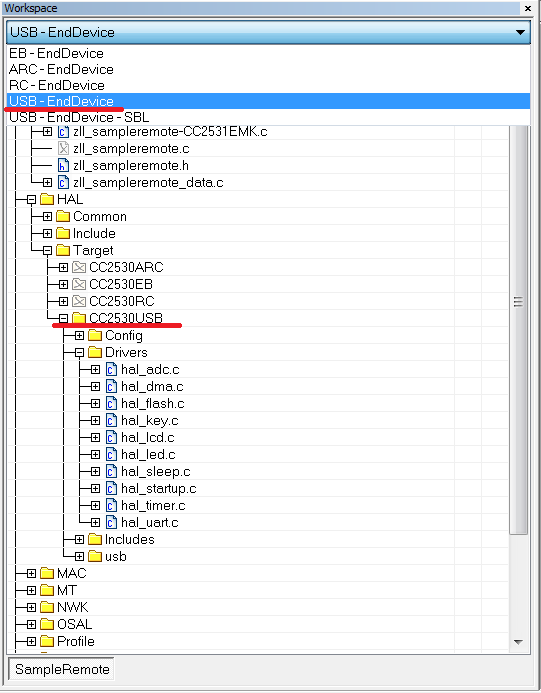
I am using CC2531 USB Dongle , and use the SampleRemote project at Texas Instruments\Z-Stack Lighting 1.0.1\Projects\zstack\ZLL\SampleRemote\CC2530DB

And I just getting started with PWM on CC2531 .

I have seen the datasheet  and also reference some information for PWM on CC2530 like the following :http://e2e.ti.com/support/low_power_rf/f/156/t/118346.aspx?pi267162=2

but I still don't understand how to use...

I found the information from the other web.

The SampleLight project choose Zlight - Router has PWM output by using Timer1 in C:\Texas Instruments\Z-Stack Lighting 1.0.1\Components\hal\target\CC2530PMP4712\hal_timer.c .

I have see the setup about Timer1 in SampleLight project -> hal_timer.c but the hal_timer.c in SampleRemote is empty.

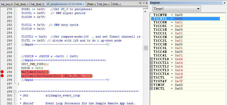
So , can I use the same code like the following for Timer1 in SampleLight project->hal_timer.c , and put in to SampleRemote ->hal_timer.c to implement the PWM on CC2531 via using Timer1 ?? or choose which mode to use , like:free-running or up/down mode ??

1.typedef struct

2.FUNCTIONS - Local

3.HalTimer1Init

4.halTimer1SetPeriod

5.halTimer1SetChannelDuty

  • Hello,

        You will need to add the CC2531 target to the SampleLight project and copy over the hal_timer.c from the CC2530PMP4712 target. The following link gives an example of a CC2531 target for the SampleRemote project.

    http://processors.wiki.ti.com/index.php/ZStack-Lighting_Kit_CC2531EMK#Generating_the_ZStack-Lighting_Kit_FW_from_ZStack-Lighitng-1.0.x_Release

    You can also look at PWM_ALT compile otion in the SampleLight project to select which port pins the PWM are generated on. For CC2531 dongle PWM_ALT may be a better option.

    Regards, TC.


  • Hi , TopCat  thanks for your reply.

    I have download the add-on-lighting-kit for CC2531 patch.

    And I also paired to the Zlight by CC2531 USB Dongle , and use "touchlink" to turn on the Zlight by following the link you pasted .


    I want to implement the PWM on SampleRemote project.

    Should I add the CC2531 target to the SampleLight project ?

    Can I copy over the hal_timer.c to CC2530USB target from the CC2530PMP4712 target ?


    You mean the xPWM_ALT2 in preprocessor ??

    But in the SampleRemote project , there doesn't has PWM_ALT. 

    Thanks !


  • Sorry, I made the assupmtion that you wanted to run the SampleLight project on the CC2531 dongle. I now see that you want to add PWM support to the remote project running on CC2531 dongle.

    Yes, what you say is correct  just copy hal_timer.c from:

    Z-Stack Lighting 1.0.1\Components\hal\target\CC2530PMP4712

    To:

    Z-Stack Lighting 1.0.1\Components\hal\target\CC2530USB

    Regarding PWM_ALT2, we use the xPWM_ALT2 as a convenient way to compile in/out these options. Remove the x, and the prject will driver the alternative PWN pins (as mentioned in the users guide). These line up better with the LED's on the SmartRF05BB/EB and the CC2531EMK (if you are interested in seeing the PWM on the LED's).

    Regards, TC.

  • Hi ,TopCat! 

    Thank You for Your fast answer.

    Yes , I have interested to seeing the PWM on the LED's.


    Maybe use the PWM_ALT2 is a convenient way , but I want to learn how to setup the register by myself like the following link.

    http://e2e.ti.com/support/low_power_rf/f/156/t/118346.aspx?pi267162=1

    Q1: Does other file should I copy from CC2530PMP4712 to CC2530USB except the hal_timer.c ??

    Q2: After I copy the file that the PWM needs from CC2530PMP4712 to CC2530USB , where should I modify the code like the register setting ?


    Thanks !

  • You do not need to modify the registers. Just use the Timer API to control the PWM:

    //Initialise

    HalTimer1Init(0);

    //Drive White Ch1 50%

    halTimer1SetChannelDuty (HAL_T1_CH1, 500);

    Regards, TC.

  • Thanks , TopCat !

    So...If I want to define the Pin of PWM output such as P0_4.

    Q1 : I need to define the following code at zll_sampleremote-CC2531EMK.c in C:\Texas Instruments\Z-Stack Lighting 1.0.1\Projects\zstack\ZLL\SampleRemote\Source?

    P0DIR |= 0x10;   //  P0_2 port 
    P0SEL &= ~0x10; 

    But...if I don't need to modify the registers. how do I know the the following register setting about PWM without using PWM_ALT2 ?

    Q2 : How do I know what the operation mode (Free-Running , Modulo or Up/Down Mode) , output compare mode am I use ?


    I want to see the waveform by using oscilloscope from PWM output PIN.

    Q3 : How do I know which port and pin is set to PWM output on CC2531 ?


    I see many define has in hal_timer.s51 at Z-Stack Lighting 1.0.1\Projects\zstack\ZLL\SampleLight\CC2530DB\ RouterZlight\List

    Q4 : Should I copy the hal_timer.s51 to CC2530USB ?

    Thanks!

  • I see the following code like you pasted in SampleLight-zllSampleLight_Init.

    halTimer1SetChannelDuty (WHITE_LED, PWM_FULL_DUTY_CYCLE);

    The WHITE_LED is define to HAL_T1_CH4 , and the HAL_T1_CH4 is define to 4.

    It set the PWM dutycycle of channel 4 is 100%.

    Is it denote the channel 4 is the PWM output ?

    But which pin is the PWM output for channel 4 ?

  • You can find this information in the CC2530 users guide (http://www.ti.com/litv/pdf/swru191d). Table 7-1 "Peripheral I/O Pin Mapping" shows timer 1 channel pins, for the primary and alt. 2 (used when PWN_ALT is defined) mappings.

    Regards, TC.

  • Thanks for you , Topcat !  It very helpful.


    And I see the following code in hal_board_cfg.h in SampleLight project , but SampleRemote project doesn't have the following code.

    #if defined (PWM_ALT2)
    #define INIT_PWM_PINS() \
    { \
    /* Drive LED1 from timer 1 ch2 and LED2 from timer 1 ch1 */ \
    /* unfortunitly we can not connect any other leds to the timer PWM */ \
    /* on the SmartRF05EB/BB */ \
    PERCFG |= 0x40; /* set timer 1 to use alt configuration*/ \
    P1SEL |= ( 0x1 | 0x2 ); \
    P1DIR |= ( 0x1 | 0x2 ); \
    }
    #else
    #define INIT_PWM_PINS() \
    { \
    PERCFG &= ~(0x40); /* bit 6 = 0 */ \
    P0SEL |= ( 0x08 | 0x10 | 0x20 | 0x40); /* P0.3:6 */ \
    P0DIR |= ( 0x08 | 0x10 | 0x20 | 0x40); /* P0.3:6 */ \
    }
    #endif

    Part1------------------------------------

    So I have to copy the above code in hal_board_cfg.h from CC2530PMP4712 to CC2530USB.

    According to the Table 7-1 and the above code in hal_board_cfg.h

    If I don't define PWN_ALT2 in SampleRemote project , the PWM output pin of channel 1 , 2 , 3 and 4 is the P0_3 , P0_4 , P0_5 and P0_6 respectively.

    So...If I set the PWM dutycycle of channel 1 for Timer 1 is 50% by using halTimer1SetChannelDuty (HAL_T1_CH1, 500); in SampleRemote project -> zllSampleRemote_Init function

    Q1 : And then I can see the waveform from P0_3 via oscilloscope when CC2531 USB Dongle power on , is it correct ?? 


    Part2------------------------------------

    If I just copy the timer.c in to SampleRemote project, and doesn't copy the above code to hal_board_cfg.h.

    Q2 : Should I modify the registers like the following code by reference the following link??(Because the original hal_board_cfg.h in SampleRemote is not define the PWM output pin)

    http://e2e.ti.com/support/low_power_rf/f/156/t/118346.aspx

    P0SEL |= 0x08;  // Set P0_3 to peripheral

    PERCFG &= ~0x40; // Select Timer 1 Alternative 0 location


    Thanks !!

    Martin


  • Q1 Yes, this should be the case.

    Q2. Yes you will need to change hal_baord_config. You will need the INIT_PWM_PINS macro, but it must also by called in HAL_BOARD_INIT. As you mentioned you should also make sure that the PWM periphral is enabled on thise pins, look at the ENABLE_LAMP macro.

    Regards, TC.

  • Thanks , TopCat

    I copy the hal_timer.c from CC2530PMP4712 to CC2530USB.

    and add the following code of red color in hal_board_cfg.h in CC2530USB.

    #define HAL_BOARD_INIT() \
    { \
    uint16 i; \
    \
    SLEEPCMD &= ~OSC_PD; /* turn on 16MHz RC and 32MHz XOSC */ \
    while (!(SLEEPSTA & XOSC_STB)); /* wait for 32MHz XOSC stable */ \
    asm("NOP"); /* chip bug workaround */ \
    for (i=0; i<504; i++) asm("NOP"); /* Require 63us delay for all revs */ \
    CLKCONCMD = (CLKCONCMD_32MHZ | OSC_32KHZ); /* Select 32MHz XOSC and the source for 32K clock */ \
    while (CLKCONSTA != (CLKCONCMD_32MHZ | OSC_32KHZ)); /* Wait for the change to be effective */ \
    SLEEPCMD |= OSC_PD; /* turn off 16MHz RC */ \
    \
    /* Turn on cache prefetch mode */ \
    PREFETCH_ENABLE(); \
    INIT_PWM_PINS(); \
    \
    HAL_TURN_OFF_LED1(); \
    LED1_DDR |= LED1_BV; \
    HAL_TURN_OFF_LED2(); \
    LED2_DDR |= LED2_BV; \
    }

    #define INIT_PWM_PINS() \
    { \
    PERCFG &= ~(0x40); /* bit 6 = 0 */ \
    P0SEL |= ( 0x08 | 0x10 | 0x20 | 0x40); /* P0.3:6 */ \
    P0DIR |= ( 0x08 | 0x10 | 0x20 | 0x40); /* P0.3:6 */ \
    }

    /* ----------- Debounce ---------- */

    add the following code of red color in zll_sampleremote-CC2531EMK.c

    void zllSampleRemote_Init( byte task_id )
    {

    HalTimer1Init(0);

         ......

    halTimer1SetChannelDuty (HAL_T1_CH1,500);

    }

    But I didn't get 50% duty cycle on oscilloscope...did I do something wrong ?

  • Maybe soething is over writing the configuration. To test this your could call  INIT_PWM_PINS before HalTimer1Init(0);


    regards, TC.

  • No...it doesn't show anything.

    Does there has the other code that I didn't add , like ENABLE_LAMP or the other??

  • Hi

    I remove the following code in zllSampleRemote_Init in SampleRemote project.

    INIT_PWM_PINS();
    HalTimer1Init(0);
    halTimer1SetChannelDuty (HAL_T1_CH1, 500);

    And I reference the registers setting at link http://e2e.ti.com/support/low_power_rf/f/156/t/118346.aspx?pi267162=1

    add the following code in zllSampleRemote_Init in SampleRemote project.

    PERCFG &= ~0x40; // Select Timer 1 Alternative 0 location
    P2DIR = (P2DIR & ~0xC0) | 0x80;
    P0SEL |= 0x08;
    T1CC0L = 0xff; // PWM signal period
    T1CC0H = 0x7f;

    T1CC1L = 0x78; // PWM duty cycle
    T1CC1H = 0x10;

    T1CCTL1 = 0x1c;
    T1CTL |= 0x0f; // divide with 128 and to do i up-down mode*/

    Q1 : Why the PERCFG &= ~0x40 is "Select Timer 1 Alternative 0 location" ?

    In User guide , page 85. The Description of number 6-bit in PERCFG is 

    Timer 1 I/O location
    0: Alternative 1 location
    1: Alternative 2 location

    So...The PERCFG &= ~0x40 is not Alternative 2 location ??


    It show the Sine wave on the oscilloscope , but it seen doesn't look like 50% duty cycle.

    Q2 : But why the duty cycle is 50% when T1CC1L and T1CC1H is 0x78 and 0x10 respectively ? How to calculated the duty cycle?

  • wun martin said:

    Q1 : Why the PERCFG &= ~0x40 is "Select Timer 1 Alternative 0 location" ?

    In User guide , page 85. The Description of number 6-bit in PERCFG is 

    Timer 1 I/O location
    0: Alternative 1 location
    1: Alternative 2 location

    So...The PERCFG &= ~0x40 is not Alternative 2 location ??

    Not sure I get this question PERCGF &= ~0x40 is clearing bit 6, so "0: Alternative 1 location" would be correct. PERCGF |= 0x40 would be setting bit 6 and so "1: Alternative 2 location" would be used.

    wun martin said:

    It show the Sine wave on the oscilloscope , but it seen doesn't look like 50% duty cycle.

    Q2 : But why the duty cycle is 50% when T1CC1L and T1CC1H is 0x78 and 0x10 respectively ? How to calculated the duty cycle?

    CH0 sets the period and CH1-4 set the duty cycle of CH1-4 respectively. As T1CC1L/H are ~12% of T1CC0L/H I would xpect a 12% duty cycle.

    I would advise that you use the halTimer API as this abstracts these calculation from the application giving a simple API. Also it is not good practise to modify register settings in your application. Could it be the missunderstanding in Q1 that meant that you where not seeing the wave form when using the halTimer API's?

    /TC.

  • Thank you ! Topcat.

    But I have try to add the following code in the end of zllSampleRemote_Init.

    INIT_PWM_PINS(); 
    HalTimer1Init(0);
    halTimer1SetChannelDuty (HAL_T1_CH1, 500);

    I still did not seeing the wave form , and I don't know why...

    So I had to modify register settings to see the wave form.

    OK , If I use the halTimer API , should I do something about ENABLE_LAMP in zllSampleRemote_Init

    I see the DISABLE_LAMP define in SampleLight in hal_board_cfg.h , and use in zll_sampleLight.c.


    Or the priority setting of P2DIR is not set to 0x80 , so I can see the wave form ?

    I didn't see the priority setting of P2DIR in sampleremote.

  • It could be that on the CC2531 dongle something is setting P2DIR incorrectly for the PWM to work, so yes include this. Also check if there are any other reg differences that can explain the issue. In IAR debug mode you can do view->registers to see the register settings.

    /TC.

  • It work successfully , it show the 50% wave form after I add the P2DIR = 0x80.

    I set the break point and see the value of registers.

    But I didn't know why the T1CC1H is 0x00 ?