This thread has been locked.

If you have a related question, please click the "Ask a related question" button in the top right corner. The newly created question will be automatically linked to this question.

SmartRF06EB stuck in XDS100v3 Advanced Mode

Other Parts Discussed in Thread: CC2538, CC1310

Hello,

I used the SmartRF06 Evaluation Board with SmartRF Studio 7.2 and I'm no longer able to communicate with the board. The equipment worked the first time I connected it to SmartRF. I only noticed the issues the next time I went to use the board. The red LED for advanced mode is on, though it doesn't look fully lit.

I've tried connecting it to SmartRF Studio but I get a message stating it has an existing flash. I select OK to delete the flash then SmartRF crashes. 

I've connected it to Flash Programmer 2 to delete the flash and I get the following message.

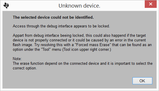
I tried Forced mass Erase but after initiating access to the target I get the following failure messages:

Create XBAL Object failed: Board reset before connect failed

Failed to create device object.

When uploading the program in Code Composer 6 I get the following message.

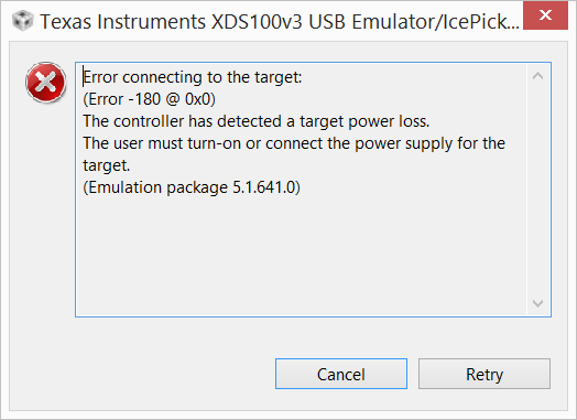
Anyone know what I can do to get the board functional again?

Thank you,
Juan

  • Hi Juan,

    Check that the "SOURCE" switch which is below the power switch, is in the USB position and not BAT. Also check that the "VDD to EM" jumper, on the right side of the board, is properly placed.

    Let me know if this fixes the problem,
    Hector
  • Hello Hector,

    Thank you for the suggestions. The source is set to USB and the VDD to EM jumper is set correctly.

    From when I last successfully used the board and when I saw the issue I didn't modify anything on the board. The last application I used with the board was SmartRF Studio 7. Could SmartRF Studio have locked it down in any way?

    Please let me know if you have other suggestions.

    Thanks,
    Juan
  • Juan,

    When you turn the board off and on again does the Advanced Mode LED stays on?
    What EM are you using?

    You can try using SmartRF Flash Programmer 2( www.ti.com/.../flash-programmer ), to erase the flash.

    Regards,
    Hector
  • Hector,

    The Advanced Mode LED turns on as soon as power is switched on. The issue occured while working on the cc1310 EM though I get the same results if I try the cc2538 EM.

    BTW the Advanced Mode LED turns on even without an EM. I have other SmartRF06 boards and I've confirmed the EMs function correctly so I believe the issue is with the board.

    I've tried Flash Programmer 2 but it fails. Please see my original post for more information.

    Thanks,
    Juan
  • Yes, the problem is with the SmartRF06 board which is what I initially thought because of the Advanced Mode LED. My guess is that there is no power going to the EM which is why I initially suggested to check the switch and the jumper.
    At this point my only suggestion is to check that all the jumpers are properly set, measure the voltage rails to see if the EM is getting power and check the solder joints on the pins for the jumpers.

    Hector
  • Hector,

    Thank you for the feedback. I'll check the power next. Straightforward enough to do on SmartRF06 board but could you provide test points on the actual EM?

    Also, why is it you think the EM is not getting power? I turned on a good SmartRF06 board without an EM and it turns on without the Advanced Mode LED. What are the requirements for the Advanced Mode LED to turn on when there isn't an EM in place?

    Thanks,
    Juan
  • Juan,

    To measure from the EM itself it will be better to use the CC2538 since it has jumper pins to select the power source, and you can measure the supply voltage on there.


    The reason why I said that the EM might not be getting power is because I have seen this happen before, for example if you turn on the SmartRF06 and take the "VDD toEM" jumper off then the EM wont get power and also the Advanced Mode LED will turn on but it is slightly dimmed, the same thing happens if you put the source switch into the BAT position, and this happens with or without the EM being plugged into the board. 


    Regards,

    Hector 

  • Hector,

    Looks like the EM is only getting 1V. When I remove the EM and test the power going to the EM interface it's 0V. I also checked on a functioning board and I get 3.3V with and without an EM. 

    Is this common? I don't remember even touching the board so I don't believe static discharge is the cause.

    Thanks for you help tracking down the issue!

    Juan

  • Juan,

    I don't think this is a common issue.
    I have seen this happen only when the VDD to EM jumper is missing or the source switch is in the BAT position.

    Hector.
  • Hector,

    I never removed the jumper nor have I ever ran the boards off BAT. Are you aware of any options to repair?

    Thanks,
    Juan
  • Juan,

    My only suggestions at this point is to take a look at the datasheet for the SmartRF06(http://www.ti.com/lit/ug/swru321a/swru321a.pdf ) and follow the schematic to debug the board and hopefully find what is the source of the problem. You can also post your problem in the tools forum http://e2e.ti.com/support/wireless_connectivity/f/155 to see if someone has had this problem before and hopefully get a solution for this issue. 

    Regards,

    Hector

  • Hector,

    Thank you for the help debugging.

    Juan
  • Hector,

    Wanted to let you know that I tried powering the board off batteries and that seemed to have reset whatever happened. The boards are fully functional on USB again.

    I was unable to find a schematic for the SmartRF06 boards. Can you point me to where I can find it? I'd like to determine why this happened and a schematic would help a lot.

    Thanks,
    Juan
  • Juan,

    You can find the schematic towards the end of this document www.ti.com/.../swru321a.pdf

    Hector.