HI Guys!
I working on to finish my dimmer device, as I told here before, I using Z-Stack Home 1.2.2a.44539 and SampleLight project as a reference.
I already have my device connected in network and sending and responding all those messages necessary to working well, including ZCL messages, as a dimmer device.
I studing Mr Yikai post here (https://sunmaysky.blogspot.com/2014/11/how-to-output-pwm-from-cc2530.html ) to see how to start timer and other parameters necessary to use PWM definitions and implement it in my dimmer device.
I would like to use P1.1 as a PWM port. To set it I used 2nd part code from YK´s post:
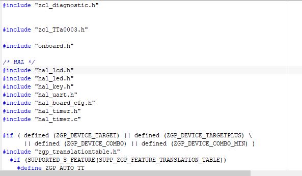
at: hal_board_cfg.h
PERCFG |= BV(6); // Select Timer 1 Alternative 2 location
P2DIR = (P2DIR & ~0xC0) | 0x80; // Give priority to Timer 1
P1SEL |= BV(1); // Set P1_1 to peripheral
T1CC0L = 0x3A; // PWM signal period
T1CC0H = 0x01;
T1CC1L = 0x9D; // PWM duty cycle
T1CC1H = 0x00;
T1CCTL1 = 0x1c;
T1CTL |= (BV(2)|0x03);
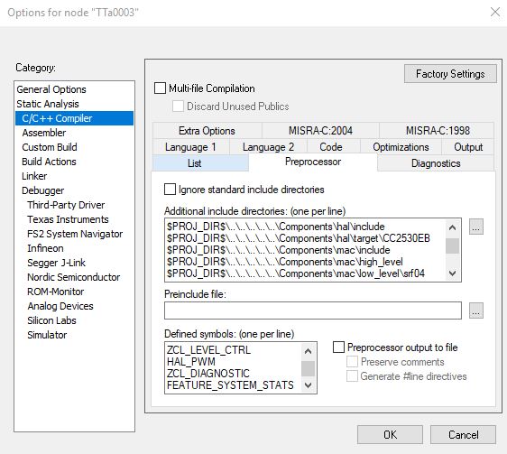
and I comment in at compile options HAL_PWM to starting to use PWM definitons in all those zstack files.
The next step, in my mind, is to set up the PWM definitions in my app file (zlc_myproject.c), and need to use some functions to set up duty cycle variations over epecific port (in my case is at P1.1). As I said that using zcl_samplelight as a reference, and in this file I´m seeing a few PWM definitions structures, as I describing bellow:
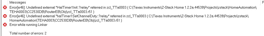
#if (defined HAL_BOARD_ZLIGHT) || (defined HAL_PWM)
HalTimer1Init( 0 );
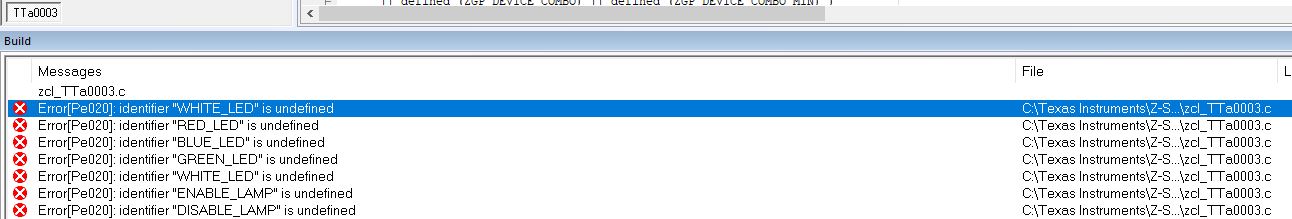
halTimer1SetChannelDuty( WHITE_LED, 0 );
halTimer1SetChannelDuty( RED_LED, 0 );
halTimer1SetChannelDuty( BLUE_LED, 0 );
halTimer1SetChannelDuty( GREEN_LED, 0 );
void zclTTa0003_UpdateLampLevel( uint8 level )
{
uint16 gammaCorrectedLevel;
// gamma correct the level
gammaCorrectedLevel = (uint16) ( pow( ( (float)level / LEVEL_MAX ), (float)GAMMA_VALUE ) * (float)LEVEL_MAX);
halTimer1SetChannelDuty(WHITE_LED, (uint16)(((uint32)gammaCorrectedLevel*PWM_FULL_DUTY_CYCLE)/LEVEL_MAX) );
}
#endif
+
* @fn zclTTa0003_AdjustLightLevel
*
* @brief Called each 10th of a second while state machine running
*
* @param none
*
* @return none
*/
static void zclTTa0003_AdjustLightLevel( void )
.
.
.
I trying understanding:
How to I link, in app definition, hal_board_cfg.h with espcific port (my case P1.1)?
I seeing WHITE_LED, RED_LED, GREEN_LED and BLUE_LED, but I can´t find in hal_board_cfg.h any correlation code line.
Each app code function is responsible for to increase or decrease duty cycle, even using WHITE_LED, RED_LED and etc...
I believe that I must not use WHITE_LED and each others LEDs or need to associate one with P1.1 port.
Somebody can give a way to understanding it to finish my project?
BR
Alex