

Often in high-power motor drives or industrial controllers, designers use closed-loop current sensors when their application requires a highly accurate representation of either AC or DC current. Also used in energy and hybrid electric vehicle (HEV) applications, a closed-loop current sensor can utilize a special sensor signal conditioning chip like the DRV411 that includes a Hall effect device as the feedback element.
In a recent user guide on a TI Design reference design (TIPD180), I explained how the circuit works when using a 5V supply and a fixed 2.5V reference. After publishing that design, I was asked, “How would the circuit work if the reference was fixed at 1.65V from an external source such as my analog-to-digital converter [ADC]?” Good question! Let’s work through the answer.
The drive stage of the DRV411, which provides current to the compensation coil, has a common-mode voltage that is fixed at VDD/2. When the supply rail is 5V, the drive-stage output has a common-mode level of 2.5V. The difference amplifier output stage of the DRV411, which provides the output voltage of the sensor module, uses the REFIN pin to set its common-mode output level. When the REFIN pin voltage is not equal to the internal VCM of the drive stage, current can flow through the series resistors in the difference amplifier, causing an offset error in the sensor module.
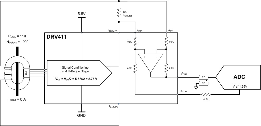
Figure 1: Uncommon VREF and VCM
Figure 1 provides an example where the DRV411 device is powered from a (max) 5.5V source; the reference is driven from an external ADC at 1.65V. The difference in voltage between the coil driver VCM and the reference is 2.75V – 1.65V = 1.10V. This voltage difference causes ~22µA of current to flow through the series resistors internal to the DRV411. Current also flows through the coil and shunt resistor, causing VOUT to be closer to 1.6513V.
When VOUT is fed into the external ADC for digitizing with its reference fixed at the original 1.6500V level, the primary current looks like it has a 1.34mV offset. Considering the 1,000 turns on the compensation coil, the 10Ω shunt resistor and the gain of four in the difference amplifier, 1.34mV of offset in VOUT is equal to about 33mA of primary current.

The TIPD180 was set up as a +/-50A sensor. Having a reference voltage lower than 2.5V will result in the sensor being able to go higher on the positive current measurements, but it will run out of headroom on the negative current measurements at around 40A.
Additional resources:
- Find out more in this app note, Design Considerations for the DRV411.
- Read more about the TIPD180, a single-supply closed-loop current transducer solution designed to accurately measure DC, AC and pulsed currents to +/-50A with galvanic isolation between the primary and secondary circuits.
- Get the most-used A/D conversion formulas in one handy guide.
