

This is the second post a three-part blog series on electrical overstress (EOS) from amplifier expert Art Kay. Get more tips on how to avoid damage from EOS from the second and third installments of Art's series.
I remember when I was in college and we somehow managed to get the 120V AC supply connected to the 5V microcontroller supply. The microcontroller exploded and little pieces of ceramic DIP shot across the lab. That was my first experience with electrical overstress (EOS).
While it may be obvious that you shouldn’t connect 120V to a 5V device, how do you know what are the safe operating levels? The answer is that the “Absolute maximum ratings” table describes the worst case input signals, supply voltages and temperatures that can be applied to a device before it is damaged. Table 1 for example shows the absolute maximum ratings for the OPA192. In this blog, let’s focus on the supply voltage and input signals. I’ll do a follow up blog that covers the other parameters.
Table 1: Absolute Maximum Ratings Table for OPA192
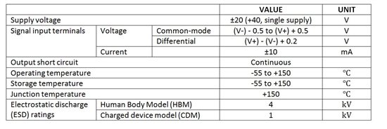
In this example, the absolute maximum supply voltage is ±20V or 40V for single supply. It is important to understand that the Absolute Maximum Supply Voltage (40V from Table 1) is different from the Maximum Supply Voltage from the Operating Specifications (36V from Table 2). Exceeding the Absolute Maximum Supply Voltage will cause damage to the device, where as exceeding the Maximum Supply Voltage from the operating specifications means that the accuracy of the device may degrade beyond the given limits. So, in this example, if the supply voltage is set to 37V the devices accuracy may be affected, but the amplifier will not be damaged.
Table 2: Operating Specifications for OPA192
Electrical Characteristics
At TA = +25C, VCM = VOUT = VS/2, and RLOAD = 10kΩ connected to Vs/2, unless otherwise noted.

Now that we understand the intent of the absolute maximum rating table, let’s consider the input signals. Figure 1 lists both a common mode and a differential maximum input. The common mode signal is the voltage seen at either input of the amplifier. The differential input signal is the voltage applied between the amplifiers inputs. When an op-amp is operating normally the differential input is the input offset voltage (Vos). In some cases, however, the amplifier may have a large differential voltage applied. For example, if the amplifier is used as a comparator or is connected to a multiplexer the input may have a large differential voltage the instant the multiplexers channels are in transition. Figure 1 helps clarify the difference between common mode and differential input.

Figure 1: Common Mode and Differential Input for Op Amps
As long as you keep the input signals less than the absolute maximum ratings, the amplifier will not be damaged. That seems simple, so why is electrical overstress such a problem? The reason is that amplifier input terminals are often exposed to the outside world. For example, a product may require a connection to an external sensor to operate. Often times the external connections can be miswired to an excessive voltage. In other cases, a brief overvoltage surge can be applied through magnetic or capacitive coupling. For harsh environmental conditions, it may be impossible to prevent the overvoltage condition. In these cases, it is necessary to use some external protection.
The simplest form of external protection is a current limiting resistor. Notice in Table 2 that the input terminal current must be limited to 10mA or less. This current limitation can be used to select a resistor that can prevent damage from overvoltage sources. Figure 2 shows the internal op amp ESD (Electrostatic Discharge) protection diodes (D1, D2, D3, and D4). The ESD diodes by themselves are not designed to handle large continuous electrical overstress currents. Rather, the ESD diodes are designed to protect against very short static discharge pulses (kilo Volts for nano-seconds). In fact, the diodes are rated to allow only a 10mA continuous input current (See Table 2, Input Terminals Current). Thus, the key to protecting the inputs is to limit the input current to less than 10mA using a series resistor (Rp). Note that you need to check the data sheet to confirm the input ESD diode configuration in the amplifier.

Figure 2: Internal ESD Diodes and Current Limiting Resistor
Selecting the value of the current limiting resistor depends on the worst case overstress voltage expected for your application. Equation 1 shows an example calculation assuming a 100V overstress voltage. The equation is derived using ohms law and a Kirchoff's voltage walk around the loop. A larger series protection resistor can be used for even higher protection levels.

One final note is that transient voltage suppressors (D5 and D6) are required on the power supply to absorb the over voltage signal. Transient voltage suppressors are similar to zener diodes but they are optimized with large junction areas to quickly absorb high power for short periods of time. These diodes are required because the power supply may not be able to sink current. Furthermore, the supply may not be able to respond fast enough to protect against the over voltage signal. It is important to make sure that you use unidirectional voltage suppressors as opposed to bidirectional for this application.
In this blog, we learned how to protect amplifier inputs from over voltage conditions using a series resistor. In a follow-on blog we will look at the other ratings in the absolute maximum table. I hope that this discussion can help you to avoid the smoke and fire that I experienced in college.
If you found this of interest, be sure to check out the other posts in my "Electrical overstress in a nut shell" series.

