

Last week we looked at two very common reasons for oscillations or instability in op amp circuits. The ultimate cause of both was delay or phase shift in the feedback path. Review it here. I confess that I had intended to discuss cures for both circuits this week. But to keep these blogs bite-size, I think it’s best to cover just one this week. (I must control my enthusiasm!)
A simple non-inverting amplifier can be unstable or have excessive overshoot and ringing if the phase shift or delay created by the op amp’s input capacitance (plus some stray capacitance) reacting with the feedback network resistance is too great. You may be able to make some improvement by reducing stray capacitance at this node, minimizing the circuit board trace area of this connection. For a given op amp, input capacitance (differential + common-mode capacitance) is a fixed value—you’re stuck with it. You can, however, reduce the resistances of the feedback network proportionally to keep the gain the same. This moves the pole created by this capacitance to a higher frequency and decreases the delay time constant. Reducing the resistances to 5kΩ and 10kΩ in this example makes a big improvement but still produces approximately 10% overshoot with ringing. It also creates additional load on the op amp, so you can’t take this solution too far. The sum of the two resistors is a load on the op amp and you would not want to be too low.
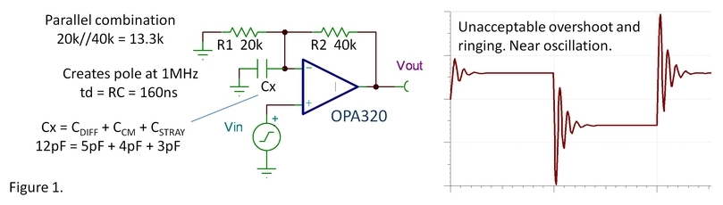
The better solution is likely to be a capacitor, Cc, connected in parallel with R2 (figure2). When R1∙Cx = R2∙Cc, the voltage divider is compensated and the impedance ratio is constant for all frequencies. There will be no phase shift or delay in the feedback network. :)

You can liken the feedback network to the compensated attenuator in a 10x oscilloscope probe (figure 3). It’s the same concept. A variable capacitor in the probe allows adjustment to make the two time constants equal. Note that the response of this scope probe does not ever appear unstable even when improperly adjusted. Why? Because it is not inside a feedback loop.
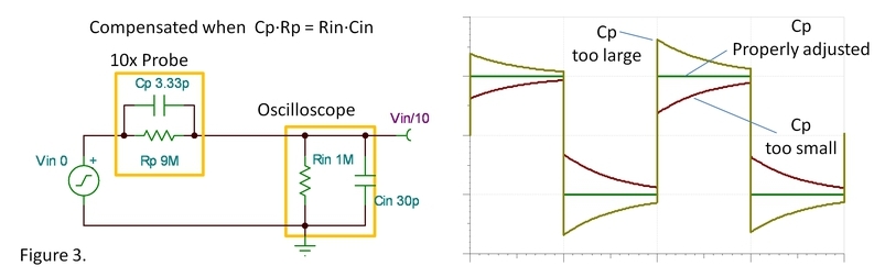
Just as one of the capacitors is made adjustable in a scope probe to fine-tune the compensation, you may also need to adjust the value of Cc in figure 2. The capacitance Cx may not be precisely known due to the uncertain effects of stray capacitance. Furthermore, you may want to tune the response of the circuit to meet your requirements with a little bit of overshoot for improved speed and bandwidth.
Last week I cited another common case of instability, an op amp with capacitive load. Again, this situation produces phase shift in the loop (delayed feedback) that is the root of the problem. This one is tricky because open-loop output resistance is internal to the op amp. We can’t connect a compensating capacitor across this resistor. In fact, it’s not really a resistor at all; it’s an equivalent output resistance of the op amp circuitry. So, next week, we’ll look at the capacitive load problem. I’ll also provide a link to a presentation with more detail on handling stability issues, so stay tuned.
Consider your last oscillating op amp. Can the problem be explained with delayed feedback?
Comments welcome and thanks for reading,
Bruce

