

I’m not referring to op amps in your parts bin. Those should be in anti-static bags or conductive foam. What about the one on your circuit board—the unused op amp in a quad or dual package. Hummm??
A recent question on our forums spurred me to address this subject but in the process, I ran across a great article by my colleague, Todd Toporski. He did an excellent job of covering the important issues and reasons. Check it out, here. I’ll summarize and add some additional thoughts.
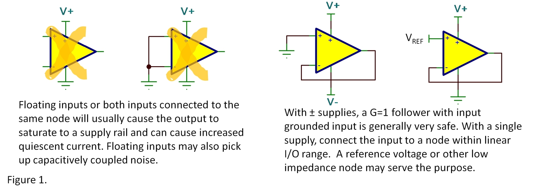
It’s best to connect the op amp in a real op amp circuit with feedback; a unity-gain buffer is an obvious choice since no additional components are required. Then connect the input to a voltage within its linear input and output range. Connections (or open-circuit inputs) that can potentially overload the input, output, or leave the amplifier in an indeterminate noisy state are undesirable.
A suggestion on circuit board layout: Position any unused op amps for possible future modifications. You may find a use for a spare op amp in a redesign or future product spin. Think ahead. Make the connections to the spare op amp on top and bottom circuit board layers where minor surgery can easily test your changes. You might even provide layout positions for feedback components with traces to tie-off nodes that can be easily cut.
Another possibility… you could avoid all these issues completely by selecting an amplifier type that has single, dual and quad versions—OPA322 is one example. This can allow an optimized circuit board layout with no orphans while using op amps with the same specs and behavior.
A word of comfort to those who may not have used a preferred method to tie off an unused amplifier: You are unlikely to greatly disturb the working op amp(s) in the same package. While you may be drawing some extra current in the unused amp, your system is unlikely to crash and burn. Most modern op amps have independent biasing circuitry, unperturbed by overloads in other channels on the same chip. If your circuits are working, relax and follow best practices in your next design.
Other readers (and I) would appreciate reading your additional tricks and ideas in comments below.
Thanks for reading,
Bruce email: thesignal@list.ti.com (Email for direct communications. Comments for all, below.)
New... Table of Contents for all The Signal blogs, organized by topic.
![]()


