This thread has been locked.

If you have a related question, please click the "Ask a related question" button in the top right corner. The newly created question will be automatically linked to this question.

Does TI have a Power Amplifier Chip Solution?

Other Parts Discussed in Thread: AFE030, OPA521, AFE031

Hi

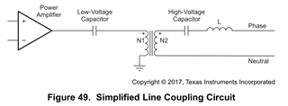
We are looking for a power amplifier  chip that delivers 1A-2A output current with protections. The input signal is a logic AND of an 88KHz PWM and a series of RS232 data, both from an MCU. The load of the power amplifier is a transformer.

Any suggestion would be highly appreciated.

Chao

  • Hi Chao,

    We are looking for a power amplifier  chip that delivers 1A-2A output current with protections.

    We have the following power amplifiers that may be able to drive the application. 

    https://www.ti.com/amplifier-circuit/op-amps/power/products.html?keyMatch=POWER%20AMPLIFIER#480=1&451typ=1%3B10&sort=451typ;desc&

    Please specify the driving voltage amplitude, frequency and current (1-2Apk?), and available input power 

    The input signal is a logic AND of an 88KHz PWM

    Please specify the transformer's driving voltage amplitude, frequency and current (1-2Apk?), and available input power..

    The input signal is mentioned above. Is this some sort of SPWM to drive the transformer? What is the transformer's operating frequency? Please specify the design requirements. 

    Best,

    Raymond

  • Hi Raymond,

    Thank you so much! I saw AFE030/031 in the list you gave. The power amp I am looking for is to replace the PA in AFE030 in our PLC application since AFE030 has not been available on the market for nearly a year. It seems OPA521 would be the best choice.

    However, I worry about the market availability once we need to buy more than10K. We tried to buy 20K AFE030 early this year, but nowhere to buy, this is the reason why we give up AFE030.

    Please give some more info on OPA521 if possible.

    Best,

    Chao

  • Hi Chao, 

    AFE031 is the improved revision of AFE030, where AFE031 will source/sink a slightly more current vs. AFE030. 

    OPA521 should work as well, even though the datasheet is specified as line driver for the PLC application. Please provide me with the definition of the PWM input signals, output frequency range and amplitude, I will send you a simulation per the requirements. 

    If you'd prefer to discuss the design via E2E private message, please let me know. I see that you have sent me a private message. 

    Best,

    Raymond

  • Hi Raymond,

    The signal to be fed into OPA521 is a combination of a PWM and a signal from UART, both generated by an MCU. The PWM is 50% duty ratio with frequency of 88KHz, and the signal from UART is a series of byte data in RS232 protocol (1 start bit, 8 data bits, 1 stop bit) in 9600 baud rate. The input signal to OPA521 is the logic AND of the PWM and the negated UART output, i.e.  PWM  AND (~UART_OUT), this is the same as the E_Tx_OUT signal in AFE030. The ampltitudes of all three signals are 0 - 5V. The OPA521 drives a transformer with (primary : secondary) ratio of  (1.3 : 1) as shown in the figure below (copied from AFE030 datasheet, Page 48), assume the frequency range of the transformer is 50KHz - 2MHz:

    Regards

    Chao

  • Hi Chao, 

    The PWM is 50% duty ratio with frequency of 88KHz, and the signal from UART is a series of byte data in RS232 protocol (1 start bit, 8 data bits, 1 stop bit) in 9600 baud rate.

    I recalled that RS232 protocol is digital signal based communication. UART is a digital communication protocol, and RS-232 is a standard for implementing UART communication in a specific way using analog voltage levels. 

    OPA521 is certainly above to drive the mentioned signal and current level, but I still have some remaining questions. 

    In the AFE031/AFE030 EVM and user guide, the FSK communication protocol is sinusoidal in nature and it is purely analog from input to output. So is the specific transformer in AFE031 EVM is designed for the FSK communication protocol. 

    https://www.ti.com/lit/ug/sbou223/sbou223.pdf?ts=1695225792479&ref_url=https%253A%252F%252Fwww.google.com%252F

    There are transformer that is designed for squarewave PWM signals, but these transformer tend to be very low input capacitance and specially designed for a driving application. such as mosfet gate driving transformer. I am not certain about ~2MHz range, but 100s kHz range are very common (if the input capacitance is high, then the output may look like sinusoidal at the secondary side of the transformer). 

    So I was not clear if the communication protocol is driven is square wave or sinusoidal waveform. OPA521 is capable to drive the transformer load as it is shown in PLC application. 

    Enclosed is the datasheet of the transformer specified for AFE031 EVM. I recalled that the magnetic may be able to handle up to 500kHz range. The magnetic core may become very lossy beyond 600kHz range or so. . 

    750510476 .pdf

    If you have other questions, please let me know. I can simulate the scenario once I have the information. 

    Best,

    Raymond


  • Hi Chao, 

    I am going to close this inquiry, since we are going to resolve the issue via email.

    Best,

    Raymond