This thread has been locked.

If you have a related question, please click the "Ask a related question" button in the top right corner. The newly created question will be automatically linked to this question.

INA333-Q1: Vcm-Vout realtion & Design problem

Part Number: INA333-Q1
Other Parts Discussed in Thread: INA333,

Hello, dear engineer;

The reason I use INA333: To measure the voltage difference induced on the coil. So the voltage difference will be very low. However, I have mentioned a few problems I encountered below:

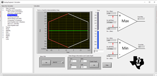
1) I entered the values for the circuit which i designed and found the relationship between Vcm and Vo through the "Analog Enginner's Calculator" program. 

After that simulated on Tına-TI. As you can see above if i use 'Vin+ = 120mV' and 'Vin- = 80mV', Vo will be 2.05V. But in my design, Vo is equal to 1.87V. 


Therefore i try to solve problem and figure something. If i add Vref value to both Vin+ and Vin-, Vo will be 2.04V. But i did not see something about this on datasheet.

Hence, may i add VRef to inputs? How can i fix this issue? ( I am open-minded to your solutions.)

2) Ref pin needs to be a low impedance node (with source/sink in current low impedance output). But i do not have enough space on pcb. So instead of using designed that i mentioned above, using the design below may accure any future problems? 

Thanks for your help. 

Best regards,

Basri KAYA

  • Hi Basri, 

    1) I entered the values for the circuit which i designed and found the relationship between Vcm and Vo through the "Analog Enginner's Calculator" program. 

    This is the Vcm vs. Vout and other input requirements for the INA333-Q1's instrumentation amplifier setup. Vref is configured at the mid supply rail, and Vref has to be low impedance node, and capable to source/sink current. So op amp Vref buffer is one of the option, or you use the equivalent band gap references. 

    2) Ref pin needs to be a low impedance node (with source/sink in current low impedance output). But i do not have enough space on pcb.

    If you do not have room to use a Vref, then you may use dual supply rails, say +/-2.75 Vdc. Enclosed is the simulation of your setup. Without the Vref, your input voltage ranges are very limited, and I need to know your coil's input voltage ranges. 


    INA333-Q1 Voice Coil 11132023.TSC

    If you have other questions, please let us know. 

    Best,

    Raymond

  • Hello,

    Thanks for the answer.

    The induced voltage on coil is a sine wave centered at Zero voltage with an amplitute of a few mv(<100mV). My aim is to shift it by Vref voltage in order to make it suitable for op-amps common mode range. How can i add the Vref voltage to the output of the coil?

    I can not use dual supply. Any suggestion?

    Best regards,

    Basri

  • Hi Basri,

    How can i add the Vref voltage to the output of the coil?

    Your drawing and simulated input are near equivalent. I think that you need to insert the Vcm = 1.65Vdc and coil voltage is riding on the Vcm mode voltage (1.65V biasing DC voltage). You will need the bias voltage for the single supply rail. It does not have to be 1.65Vdc, it can be lower, say 1V dc range. Please check with the analog engineer's calculator. 

    I do not know what the coil's winding resistance it. Please make sure that the DC bias current to the coil should be very small, may be in mA or sub micro mA ranges, Please check on the coil's datasheet, see the simulated input. 

    INA333-Q1 Coil 11142023.TSC

    If you have other questions, please let me know. Please close this inquiry once the issues are resolved. 

    Best,

    Raymond

  • Hi Raymond,

    I was looking for your drawing. Thanks for answer.

    Coil's winding resistance is nearly 250 ohm. is resistor value of 10k suitable? 

    Best regards,

    Basri

  • Hi Basri, 

    The biasing current on the coil is approx. 1.65V/10k = 1.65mA currently. Please try 100kΩ resistor in series with the coil at Vbias = 1.65V, this will reduce the bias current to approx. 16.5uA. I am guessing the application right now. The biasing voltage provides simply bias voltage to the coil. Please check with the  coil's datasheet.

    What type of coil do you have per the application? Is it audio application? 

    Best,

    Raymond 

  • Hi Raymond,

    Thanks for answer.

    There is not coil's datasheet because i wind coil by myself. The application is to measure the voltage difference in electromagnetic field induced on the coil.

    Best regards,

    Basri

  • Hi Basri, 

    I see, you may calculate the inductance from the coil and simulate the inductance in series with 250Ω in Tina simulator. 


    Please make sure that rate of change in di/dt in the coil is gradual and small. There is no input voltage spike protection in the simulated circuit.

    If you have other questions, please let us know. 

    Best,

    Raymond