This thread has been locked.

If you have a related question, please click the "Ask a related question" button in the top right corner. The newly created question will be automatically linked to this question.

INA240: Problem with reading current output during bulk current injection (BCI) test

Part Number: INA240

Tool/software:

Hello everyone,

I have problem about reading the current output during BCI test (0-400MHz, 100mA). You can see my INA240 design below. I design the input as a kelvin connection and same layout for both INA. 


I tested my product to make sure that  everything was working correctly before test process. During BCI test, my current output is setted to %100 duty cycle so there is not a software errors (pid or feedback). I shared my datas,which loged during test, below. I hope you can see it clearly.


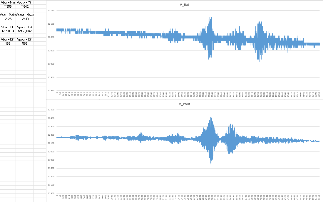
My output cables are connected to two valves which input resistor is 20 ohm and output voltage is the "V_Pout". Hence, I expected to see 590-610 mA current output on the logs. Also, I used there multimeters to measure current value of valves to make sure they have same value as logs.


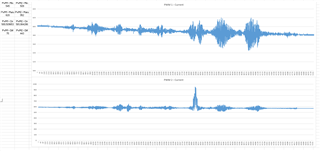
Multimeter values of current outputs:

Minimum Maximum Average
PWM 1 0.569 mA 0.601 mA 0.581 mA
PWM 2 0.566 mA 0.602 mA 0.577 mA

As you can see above, I am reading current outputs different between my board and multimeters. Logs shows me that I am reading different values for PWM1 and PWM2 also maximum and minimum values for these outputs are very different from multimeters values. This values proves me that I have problem while reading the current output.

Here is my questions:
1) I have same layout and circuit for both output. While I set the both output to same value, why am I reading different values from INA240?

2) What is the reason that I am reading the different values from my board and INA240? How can I solve this problem?

Please, do not say the reason is layout. I followed your circuit design for INA240.


Best Regards,

Basri KAYA

  • Hello Basri,

    1) I have same layout and circuit for both output. While I set the both output to same value, why am I reading different values from INA240?

    Are you using the same Rshunt?  What is the specification of the Rshunt?  This is normally the biggest error source.

    2) What is the reason that I am reading the different values from my board and INA240? How can I solve this problem?

    If the error is from RShunt then getting a better Rshunt would help.  Another is calibrating the system so they match.

  • Hello Javier,

    R185, 0.02 ohm, is my shunt resistor. I am using the same resistor for my both channel. You can find my resistor's link below. PWM1 channel is reading correctly. Of course, there will be erroneous readings during testing. But why there is more distortion in PWM2.

    https://www.digikey.com/en/products/detail/bourns-inc/CRA2512-FZ-R020ELF/1775030

    I am not using any resistor R219 and R221 for input channels for that is not the error minimum? What did you mean by calibrating the system?


    For my second question, I said it wrong. What is the reason that I am reading the different values from my board and multimeters? Multimeter's value and log showsme that output of INA240 has a reading problem during BCI test.

    Alsa, I can test your suggestions on my board. I tested and will be tested so many variants untill your reply.

    BR

  • Hello Basri,

    I misunderstood. Is the proximity of the switching closer on PWM 2 vs PWM1?  Is the PWM the same for both of the signals.  This could be a VMC transient that is worse on PWM 1 vs PWM 2.  I know you did not want to blame layout but is there a difference between the two layouts?  With high frequency switching some things can get coupled in more easily depending on your layout and component placement.  Is the PWM frequency high?  

    Regards,

    Javier

  • Hello Javier,

    The PWM for both channel is %100 duty cycle (I can drive 0-1 kHz normally and I am not switching for this test.) so frequency is not important for my test process. There is not any software effect over PWM signal. For switching process, I am using BTT and the output of BTT connects to shunt resistor. Other point of shunt resistor(PWM1.CON, PWM2.CON) connects to the valves. I hope you can understand my circuit.

    For this situation, I am driving PWM1 and PWM2 with maximum 12.150V. If I have 20 ohm valve resistance, I must read 607.5 mA current from INA. In my datas, You can see that PWM2's maximum value is 952 mA which is impossible because my power supply is 12V. 


    In the begining, I did one more test before changing my pcb's layouts. Also this test was awfull and I figured out that there was a problem about via placement. GND  and VCC vias were so far from IC. After this changes, I was expecting better results but nothing changed. 

    For me, there is not any difference in layout for both channels. I can share layouts with you, it is fine.

    Best Regards,

    Basri

  • Hello Basri,

    Does the 952mA peak correlate with something in your system?  You stated that the value is impossible but something is causing the output to move much more on this than the other version.  Are the Rshunts connected the same way?  You stated the PWM is not running but is this during a transitions?

    You can see that PWM2's maximum value is 952 mA which is impossible because my power supply is 12V. 

    Can you please explain how I can say this is not possible by knowing the 12V is your power supply.  I think I would need to know more detail in your design.  

    If you can share your layout and please show the INA240, and the connection of the Rshunt.

    Regards,

    Javier