This thread has been locked.

If you have a related question, please click the "Ask a related question" button in the top right corner. The newly created question will be automatically linked to this question.

INA125 single supply issue

Other Parts Discussed in Thread: INA125, INA122, REF5050, INA826, INA333, INA331, INA332, INA321

1st post here

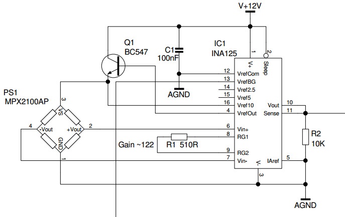
I'm building a pressure sensor circuit with the INA125 and a single supply. (See diagram)  I did some searching here but could not see a solution.

I have it connected according to FIGURE 5. Single Supply Bridge Amplifier

The supply is really 13V to make sure I have enough after the voltage drop in the transistor. Nothing is connected to pin 13 (just in case) possible use as reference voltage for another circuit if it doesn't mess things up with this part of the circuit.

With the sensor connected I get the following:

Sensor supply 10.02V

Vout+ > V+in pin6 4.76V

Vout- > V-in pin7 4.33V

Output 11.95V

With the sensor disconnected I get the following:

Sensor supply 10.02V

Vout+ 5.03V

Vout- 5.0V

V+in pin6 0.27V

V-in pin7 1.52V

Output 11.89V

There seems to be a large voltage difference at the input of the chip messing up the sensor?? I tried another chip with the same results.

Any hints on getting it to work please? It's a new design and I like to use the chip as it keeps everything in one package. Additionally I have another project in the wings with a similar set if I get it to work.

  • Hello John,

    The proper way to determine an approximate value of the initial input offset voltage of the INA is as follows:

    1) Disconect the sensor from the INA125
    2) Short pins 5, 6, and 7 to a precision supply voltage set to 6V (mid-supply given a single 12V supply).
    3) Place the device in a large gain (e.g. 2,000V/V to 5,000V/V).
    4) Measure the output (which is pins 10 and 11 shorted). The approximate input referred offset will be Vos=(Vout-Vref)/G.

    This should give you results more in line with the data sheet specifications (+/-250uV to +/-500uV depending on grade). Please let me know the results of this measurement and calculation.

    However, I am very concerned that when you disconnect pins 6 & 7 from the sensor you read 270mV and 1.52V. According to the schematic the only connections are to +Vout and -Vout. So, have you tried debugging the PCB? Perhaps you could remove the INA125 and sensor and then measure the nodes...there should be no potential present.

    This brings up one more idea: though you have tried different INA125 devices, have you tried multiple PCBs?  

  • Hi Pete

    Thank you for the reply. Just to put things in perspective the circuit is a Veroboard prototype using PDIP chips, a proper PCB will be designed once the client is happy with the results as they will be doing the digital part of the circuit. So no other boards.

    I did manage to get it "working" last night after posting the above, I ran a sharp knife blade between the tracks and re-cleaned the bottom of the board, there could have been an invisible short somewhere. I looked at that many times but could not see a thing.

    During the search here a discovered the offset adjustment trick in another thread using a pot and a resistor to one of the output legs of the sensor, this made the circuit a bit better but I think I need to use a lower value resistor (used 100K from the centre of the pot.)

    So it it mostly working as it should however I think the client has supplied me with a sensor not sensitive enough for his purposes as it needs a lot of pressure to get a bout 1V of output change instead of about 4+V (40mV max output x ~122 gain), so I'll need to speak to the client to see what happened.

    Sorry, I don't quite understand the need for the tests you mention above. :-) but, like the terminator, "I'll be back" if I'm stuck again.
  • Hello John,

    Good to hear you got it "working"! Sometimes those veroboards and protoboards (or breadboards) make things a little more complicated than they need to be.

    The purpose of the test I outlined was to determine if the offset was due to the INA. Measuring the voltage at each input of the device is not the proper method for measuring the offset. You need to short the inputs to mid-supply, connect the INA reference to mid-supply, and then measure the amplified offset voltage at the output. So, the idea was to eliminate the device as the culprit of the differential voltage.

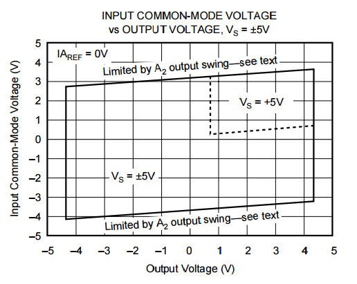
    Also, just to make sure, please understand that the linear output swing of the INA portion of the device depends on a number of things, including supply voltage, reference voltage, and input common-mode voltage. Given a single supply of 12V and Vref=0V, the INA125 Vcm vs. Vout relationship will be similar to the dotted line in the figure below (of course you have to extrapolate it for 12V instead of 5V).

    Finally, what is the intended purpose of the transistor in your circuit?

  • The purpose of the transistor is to boost the current to the sensor according to FIGURE 4. Reference Current Boost.
    If I understand the data sheet correctly the max reference current is 5mA (IL = 0 to 5mA) but the sensor needs 6mA at 10V. (~ 1.6KOhms)

    The output swing required is only 0V (or near) to 5V so it should be OK. No problems if I need to add another stage for a higher output swing and reduce the swing from the INA.

    I'm pretty much certain that the sensor is either the wrong type (ordered wrong or supplied wrong) as it is supposed to give me a maximum 40mV at max pressure and a +-2mV offset at min pressure but I get 40mV without any pressure instead of 2mV which is easily adjusted by the pot and resistor as above.

    Of course the sensor could just be faulty (or damaged??), the amplifier is working well as I get around 5V with the sensor outputting the 40mV and about 100mV with the output sensor pins shorted to each other.
  • Meanwhile back at the range....everything is doing it's job, well maybe except the guy who ordered the sensor. Been re-reading the data sheet for the sensor.

    The sensor is an Absolute type which is a vacuum sensor and it expect a vacuum at it's port in order to reduce it's output. So the 40mV is correct without any vacuum, it would decrease it's output as the vacuum increases. The Gauge (Gage) type is what should have been ordered which will increase it's output with raising pressure.

    Can't kick the client for ordering the wrong part I guess. :-)
  • And just to put this to bed....With the new and correct pressure sensor everything is working well.

    However as the sensor is now 5V I don't really need the INA125. Is something like a INA122 recommended for new designs?

    Still available from  Digikey and cheaper then the INA125.

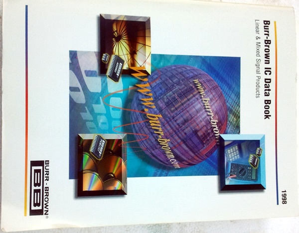
    By the way I dug out my 1998 PAPER Burr Brown catalog with all this stuff in it  :-)  it must be worth a fortune I guess.

  • Hello John,

    Good to hear it's working as intended!

    The selection of the INA depends on a number of things. What is special about the INA125 is the integrated bridge reference voltage. If you don't need it (or want to use an precision external reference like the REF5050), you have many more options.

    The most cost efficient option is likely the INA332, but it has poor CMRR and very large offset voltage. The INA331 is a better option for the value. The INA826 and INA321 are good choices as well. I would likely select the INA333, however, because it has very low offset voltage and offset drift. Note that some of these are 5V devices.

    Hope this helps! It would be interesting to see that old catalog!
  • Thank Peter

    I'll keep the INA333 in mind for the final stage of the design.

    Unless you come to Sydney (Australia) the best I can do is this: