This thread has been locked.

If you have a related question, please click the "Ask a related question" button in the top right corner. The newly created question will be automatically linked to this question.

TLV8544: PIR Motion Detection Refence Design Application Problem

Part Number: TLV8544

Hi,

I tried the circuit depicted on below image with TLV8544;

I can capture the motion very well but there are some issues. In the idle state (no motion) there is a 0-2.3V 50Hz square-like wave noise in the whole circuit. I tried different PIR sensors (Murata IRS-B210ST01, Xlitas LHI 968 and non-branded Chinese sensors) but the result is same. I used RC low pass filter with 1.5 MO and 100nF the eliminate noise. Low pass filter is located after Pin 7. I worked but circuit is not stable. I still have no idea why there is noise. 

In this image you can see the 50Hz noise after motion detection on pin 7.

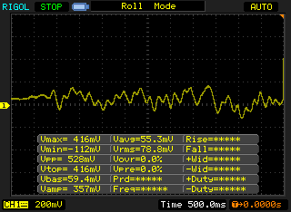
Closer look to noise signal on pin 7.

On the other hand, I can not be sure, is this circuit stable (with low pass filter) . After motion detection, I still capture logical one from outputs for some reason and there is no pattern. It stabilizes after sometimes but there is no certain time for stabilization. When I connect any of pins to oscilloscope circuit works like a charm (oscilloscope and circuit grounds are seperate) so I can not see where is the problem. How can I develop a PIR circuit that I can totally trust? 

  • Batuhan,

    Since this circuit has a very high gain (over 48k V/V), it is susceptible to the problem you are describing.  Each amplifier stage has a gain of approximately 220 V/V and the 50Hz noise that you are observing is most likely coming from the lights or power line in your lab.  Here are some simple experiments to run in order to determine the source of the noise and where it is entering into the circuit.  One simple experiment that you can do is to place a steel can like a coffee can over your circuit board and ground the can.  I am not sure how you constructed your circuit but if you are using a bread board, wires, and discrete components, the wiring can be acting as an antenna for the 50Hz noise.  If your circuit wiring is picking up the 50Hz noise, placing the grounded shield over your circuit should solve the problem.  The other potential source of the noise is your power supply.  A second experiment would be to use two AA batteries in series to power your circuit.  If the 50Hz is coming from the power supply that should eliminate the problem.

    In addition to the suggestions above, I would always recommend building the circuit one stage at a time.  Your idea of putting a low pass filter in the circuit is valid but you are placing it after the amplifier stages.  At that point you are only masking the problem.  If you can find the source of the noise or how it is entering your circuit, you can eliminate it or reduce it more effectively.

    I will leave this post open to see how your experiments go.  Please let me know if you are able to discover the source of the problem. 

  • Hello Chuck,

    Sorry for the really long reply. I could not shield the breadboard (it did not work actually, 50hz noise was still there) so I decided to print the circuit. I just had enough time to print the PCB. I made two PCBs (for XLitas LHI 968 and Murata IRS-B210ST01-R1). 


    Here is the schematic for the circuits.

    Murata sensor did not go well because of circuit and soldering issues. Circuit is not stable for now. If I have time I will print it again. 

    XLitas sensor has some issues also. I can get pretty decent outputs from the source pin of the sensor, pin 1 and pin 6 from TLV8544 but there are problems on pin 7 output.

    Pir output with motion, you can see the wave:

    Pin 1 output of the TLV8544 with motion:

    Pin 6 output of the TLV8544 with motion, you can see that voltage is lower then pin 1 output but waves are more noticable:

    Pin 1 and 6 together with motion:

    Pin 7 output of TLV8544 with motion, it works as expected when there is motion:

    If there is no motion pin 7 output is noisy because of this motion LEDs are blinking all the time:

    I want to ask few things:

    - Is voltage differences between pin 1 and pin 6 bad thing?

    - How can I go step by step to build proper PIR circuit not just copying the reference desing?

    - How can I eliminate the pin 7 output noise?

    Thanks.

  • Batuhan

    sorry to hear that you are struggling with this.  I can see that you are putting a lot of effort into getting your circuit working.  Pin1 and pin 6 should not look the same.  In an ideal circuit, pin 6 is virtually shorted to pin 5 which is your VCC/2 signal.  Remember the negative feedback of the circuit forces pin 5 and pin 6 to look like a virtual short.  So you would not expect the output signal of your first amplifier stage to look anything like the signal on pin 6.  it is necessary to set the common mode for the second amplifier stage because we are ac-coupled to the first amplifier stage.

    Everything in your circuit looks fine except I do not see a value on R2.  what value are you using there?  that is the source pin of Q2 and it is necessary to have a DC path to ground at that point.  Ideally the DC value should be around VCC/2.  You just need to have enough room for the sensor output to swing.

    I see that your PCB is a single layer board and that doesn't help your high gain, high impedance circuit.  If you can put that board in a metal can, like a coffee can, and ground the can you will probably see a significant reduction in noise pickup.  The traces and the high impedance components are picking up noise.  And since it is a single layer board, you do not have the benefit of a ground plane shielding the bottom half of your circuit.

    I still suggest you see how your circuit performs if you shield it in a can, but if that is still not possible for your here are some suggestions.

    I would build your circuit, one stage at a time.  So disconnect amplifier 2 from amplifier 1 and look at the output.  And for starters, be less concerned about the power consumption and make your components an order of magnitude smaller.  This will help you see firsthand which part of your circuit is most prone to the 50Hz pickup. When evaluating amplifier stage one, make sure amp 2, amp 3, and amp 4 have steady outputs.  I suggest you force the inputs to ground or VCC so the outputs are not oscillating.

    If this does not help your cause, I suggest you bias the sensor with more current.  this will give you more signal from your sensor and now you can reduce the gain of your amplifier stages.  I am not sure what range you are trying to achieve but this would be a good place to start.  get as much signal as possible from the sensor, minimize the gain in your two amplifier stages, and this will help desensitize your circuit from the 50Hz pickup.

    Chuck