This thread has been locked.

If you have a related question, please click the "Ask a related question" button in the top right corner. The newly created question will be automatically linked to this question.

LMP8601: Problem with LMP8601 in bidirectional configuration with reduced gain

Part Number: LMP8601

Hello,

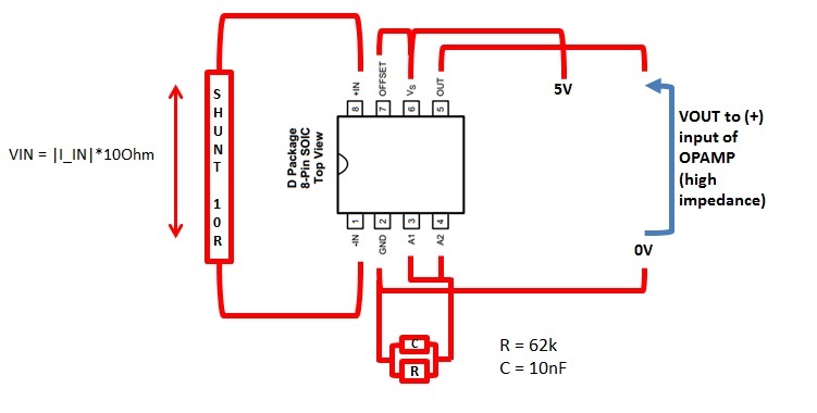
I'm using following circuit for bidirectional current monitoring using LMP8601MA.

With these values, I'm wondering to obtain a Gr = 7.654   and output offset of Vs/2.

Input current range is +/-20mA, I used 10Ohm shunt resistor and a reduced gain in order to have an output range between 0-Vs, centered around Vs/2.

At 0mA, I expected output voltage of VCC/2, but I measured 0V. With +10mA, the voltage was 0.186V. I verified all connections and everything is ok.  

After that, I tried to remove the 10nF, but nothing changed. Next step, I removed the 62kOhm resistor, knowing that the gain will be standard value G=20.

In this configuration, the output voltage since at 0mA was Vs/2, and it works fine giving positive and negative current (I set lower values to avoid output saturation).

I don't understand why my configuration doesn't work. Is there any limit in reducing gain? Bidirectional configuration is compatible with reduced gain application?

Please, help me to solve this issue.

Best regards.

  • Hello Andrea,

    Thanks for considering to use Texas Instruments in your design. I do not see an issue with your schematic, but I am going to consult with my team to see if they have any possible explanations for this. In the mean time can you confirm that your grounds pins and traces all pass a continuity test? I suspect that the ground pads to your R and C may be disconnected from the supply ground.
  • Hello Patrick, thanks for the answer.

    I explain what I did.

    After having problems I posted, I've just switched-off the supply; I removed capacitor, I've switched-on again and it was still working bad. Later on, I switched-off, I removed the resistor, I switched-on and it started working properly. 

    Anyway I will check connection as you suggested.

    If you have other info, please let me know.

    Thanks.

    Andrea

  • Hello Andrea,

    Have you made any progress on your debug? My team thinks that behavior is odd. Alternative things to try for troubleshooting include replacing the part, testing a different board, and shorting A1 and A2 to ground to see if you get similar results.

  • Hello Andrea,

    I have not heard any updates from you in a while. Consequently, I presume you had either a board issue, a short, or a defective device. If you have ruled out all of these possibilities and are still getting an incorrect output, please respond below and give me any relevant details you can. Otherwise, I am closing this thread for now.
  • Hello,
    I replied twice times the configuration I wrote in previous post (without the capacitor only 62k resistor) on a little bread-board using other 2 LMP8601 and the result is always the same.
    If I put the 62k resistor between pin 3-4 and pin 2 (GND), the output (pin 5) is always at 0V with 0mA current, even if the pin 6 and 7 are shorted to Vs=5V (I expected Vs/2 at output pin).

    So, up to now, I’ve tested 4 components and all 4 have same behaviour.
    I think I’m unlucky or maybe the reduced gain application doesn’t match with bidirectional current configuration.
    Can you verify it or try by yourself this configuration?

    I hope we will find an answer to it or I think I've to switch to a different solution/product because we have to deliver the design as soon as possible.

    Thanks.

    Best regards,
    Andrea Rossi
  • Hello Andrea,

    So I just found out a colleague of mine has experience with this issue. Turns out this is expected behavior from the device. It is something that we need to update in the datasheet. My colleague told me that the bidirectional configuration is not compatible with reduced gain. I apologize we did not alert you sooner.

    As such, I understand you may want to change to a different device. However, we think that you could still use the LMP8601 with the default gain if you adjust your shunt resistor.
  • Hello,

    thanks for the answer. It's not good news for me but I can find a different solution.

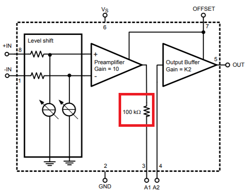
    Just a question. Can I use output A1 (gain x 10) connecting it to a non-inverting terminal of an opamp? 

    This will be useful for me avoiding to reduce not so much the shunt resistor.

    Thanks in advance.

  • Hello Andrea,

    I took some measurements in the lab and I do think that you may be able to use the A1 output.  However, you will need to have a very large impedance between A1 and ground in order to use this as an output.  This is because of the internal 100K resistor between the preamplifier and the A1 pin.  To get less than 1% difference from the preamplifier output you will need at least 10 Megohm.