Hi team,
My customer is considering two TAS5828M for their BT speaker. One for Tweeter and One for Woofer.
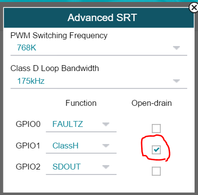
They will use Class-H control. And as far as I know, Class-H senses input signal and generate feedback signal to the external DCDC.
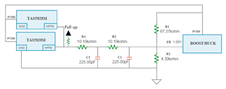
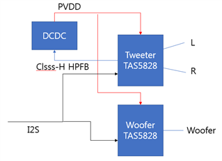
Q1. If you see in customer's configuration as below, they will share I2S input and PVDD power rail. In this case, which amp's HPFB should good to be used? For Woofer, Bass range will be boosted a lot.
If Hybrid pro algorithm only cares input signal, it seems to be fine to select any of them like below. But if Hybrid-Pro algorithm automatically considers EQ and DRCs too, than Isn't it going to be clipping on Woofer amp?
Q2.Does Hybrid-Pro algorithm consider/foresee boosted EQ gain/DRC in order to prevent clipping at output? Or just senses input signal only?
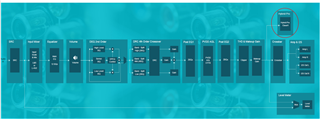
Customer's configuration:
Thanks,
Jay