This thread has been locked.

If you have a related question, please click the "Ask a related question" button in the top right corner. The newly created question will be automatically linked to this question.

ADS8354: Can't change all values in CFR register

Part Number: ADS8354
Other Parts Discussed in Thread: TMS320F280049

Hello,

I have a microcontroller, that communicates with an ADS8354. I want to change the configuration to:

RD_DATA_LINES = 1,

INPUT_RANGE = 1,

REF_SEL = 1.

Therefore I have to send the following word to the ADS to change the configuration: 1000110010000000b + 0x00h (32bit total)

After sending this configuration, I want to check if the configuration is right and send: 0011000000000000b + 0x00h + 0x00h (48bit total)

The ADC answers in the next Frame with: 0000010000000000b + 0x00h + 0x00h (48bit total)

That means only the configuration of RD_DATA_LINES was set. I would expect that  RD_DATA_LINES , INPUT_RANGE and REF_SEL are all set.

What am I doing wrong?
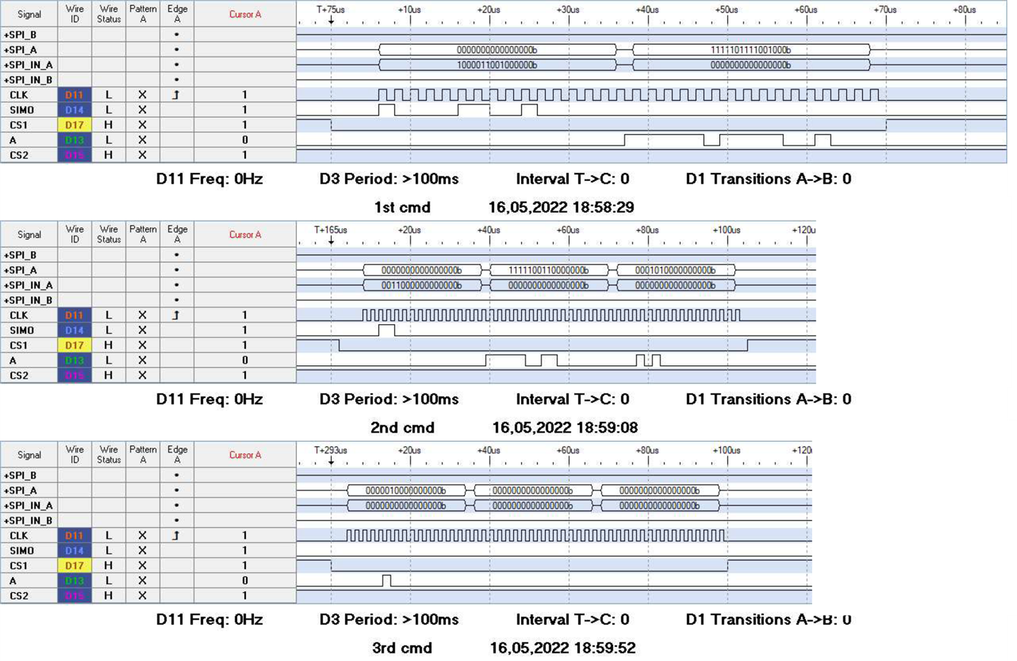
Legend:

A (SPI_A) is the SOMI line,

SIMO (SPI_A_IN) is the SIMO line.

CS1 is chip select and CS2 is not relevant in this case.

Thank you very much

Sebastian

  • Hello Sebastian,

    Thank you for your post.

    I believe there is a mistake in the write command you shared below. It looks like the bits you are writing (B[11:0]) are shifted to the left by one bit. The correct command would be 1000011001000000b (bold represents the first four command bits B[15:12]).

    Therefore I have to send the following word to the ADS to change the configuration: 1000110010000000b + 0x00h (32bit total)

    *Edit* - looking more closely at the SPI capture, it appears the text above was just a typo. If that's the case, it seems as though the SDI frames are being sent correctly. It may only be the readback that is not working. After sending the read command, the response in the next frame should begin with 0011b (R[15:12]). Let me continue to look into this more closely and get back to you with other suggestions shortly.

    Regards,

    Ryan

  • Hello Ryan,

    thank you for the answer. The wrong command that I wrote in the post was indeed a typo.

    I use SPI Mode 0, is this the correct setting for the ADS8354? I couldn't find that explicit in the datasheet.

    Also is it possible that I damaged the ADC by applying an input signal that has a common mode voltage that is higher than Vref/2? The voltage at AINP and AINM respectively, was always < AVDD though.

    Regards,

    Sebastian

  • Hello Sebastian,

    The interface on most SAR ADCs does not follow a conventional SPI mode configuration. Instead, we specify the clock edges used for data launch and data capture separately for SDI and SDO.

    I'll include the figure below as a reference:

    Data on SDO is launched on the SCLK falling edge and should be captured by the host controller on the subsequent SCLK rising edge. I think this most closely follow SPI Mode 3 (CPOL and CPHA = 1) since the rising edge would also be the trailing edge. You can use the Data Launch tables in the data sheet to know exactly when each bit on SDO is launched. 

    For SDI, the ADS8354 will capture data on the SCLK falling edge. Data must be valid at least 5 ns before and remain valid 5 ns after the SCLK falling edge (i.e. setup/hold times). The controller should change SDI on the SCLK rising edge. This mostly resembles SPI Mode 1 (CPOL = 0, CPHA = 1).

    Do you think this may be the cause of the register read/write commands issue? 

    Best regards,

    Ryan

  • Hello Ryan,

    Thank you for the explanation.

    I tried the different modes and I got it working somehow. I changed my microcontroller (TMS320F280049) to Mode 3 (Falling Edge With Delay. The SPI transmits data one half-cycle ahead of the falling edge of the SPICLK
    signal and receives data on the falling edge of the SPICLK signal. -> Definition in the datasheet of TMS320F280049) for writing the informations to the ADC and it seems to work. The response from the ADC is 0000011001000000b. So the data is there, but I would expect to receive 00110110010000000b (See table 9 in ADC datasheet). This problem seems to have happened before:

    https://e2e.ti.com/support/data-converters-group/data-converters/f/data-converters-forum/796668/ads8353-cfr-register-data-read-back

    For reading I have to switch the mode.

    Best Regards

    Sebastian

  • Hi Sebastian,

    This definitely sounds like progress. Do you see the correct response on a logic analyzer and perhaps the MCU is just not capturing correctly (i.e. missing the first few bits of the response word 0011b)?

    Regards,

    Ryan