This thread has been locked.

If you have a related question, please click the "Ask a related question" button in the top right corner. The newly created question will be automatically linked to this question.

ADS1263: Do we have any software example to calculate current using ADS1263 in diff end mode ?

Part Number: ADS1263
Other Parts Discussed in Thread: INA228

Tool/software:

Hello,

I am using ADS1263 for the current measurement.

My team mate has already raised a ticket having hardware queries about ADS1263,

Ticket link : https://e2e.ti.com/support/data-converters-group/data-converters/f/data-converters-forum/1356613/ads1263-to-measure-1ua-to-15a-dc-current-using-ads1263/5197919?tisearch=e2e-sitesearch&keymatch=ADS1263#5197919

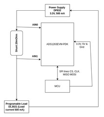
I have connected 20mOhm shunt resistor between the AI0 & AI1 pin of ADS1263.

The ADS1263 config is as below, 

Gain : 32, Datarate : 4800 SPS, Ref Positive : 2.5V Internal. Neg Positive : 2.5V Internal

AI0 as Positive Input & AI1 as Negative Input, Conversion Delay : 35 us, Digital Filter : Sinc4

I have used a DP832 power supply & DL3021 DC load, a Power supply input voltage 3.3v & current of 500mA.

I have calculated shunt current as Shunt voltage difference (Read by ADS1263) / Shunt resistor.

Please let me know if my understanding of calculating current from shunt voltage difference is correct or not.

Can you please suggest any other equation to determine shunt current from shunt voltage ?

Do we have any example application notes to calculate current from voltage difference ?

The Calculated current vs Actual current are as below,

Actual current : 5 mA | Calculated current : 8.1 mA

Actual current : 10 mA | Calculated current : 8.6 mA

Actual current : 50 mA | Calculated current : 10 mA

Actual current : 100 mA | Calculated current : 15 mA

Actual current : 500 mA | Calculated current : 45 mA

  • Hi Jagir Mehta1,

    Can you send a schematic of your system so we can review?

    I have calculated shunt current as Shunt voltage difference (Read by ADS1263) / Shunt resistor.

    This is correct, assuming you have converted the ADC code value correctly to a voltage. Can you provide the raw hex data you receive from the ADC for each measurement range e.g. 5 mA, 10 mA, etc.? Also, can you confirm that the shunt value is 10mOhm? If so, are you measuring the actual shunt value with a precision DMM first so you know its actual resistance e.g. it could be 9.9mOhm for example, which would affect your measurement accuracy.

    -Bryan

  • Hello Bryan,

    Please find below raw hex data from ADC for different input current range.

    .--> 500 mA Input current

    Volt in Hex [0xc3eca]

    Volt diff [0.000934] V 

    Shunt Current [0.046712] A

    --> 100 mA Input current

    Volt in Hex [0x3c5b4]

    Volt diff [0.000288] V 

    Shunt Current [0.014390] A 

    --> 50 mA Input current

    Volt in Hex [0x2ce79]

    Volt diff [0.000214] V

    Shunt Current [0.010706] A 

    --> 10 mA Input current

    Volt in Hex [0x221d6]

    Volt diff [0.000163] V 

    Shunt Current [0.008134] A 

    I have used the below equation to get voltage from ADC output.

    Voltage = (ADC_Output * Ref Voltage) / ADC_positive_step_count

    Reference voltage = 2.5V

    ADC_positive_step_count = 0x7fffffff (positive num range of uint32)

    I have used 20 mOhm shunt resistor.

  • Hi Jagir Mehta1,

    The data values you provided are only 20 bits (e.g. 0xc3eca]), while you should be getting 32-bit values from the ADS1263. Can you please provide the complete 32-bit value you receive from the ADC, even if the first few bits are 0?

    -Bryan

  • Hi Bryan,

    I have changed the configuration a little bit as described below,

    Shunt : 20 mOhm
    Gain : 2 V/V
    Data-rate : 4800 SPS
    Ref Positive & Negative : Internal 2.5V
    Conversion delay : 35 uSec
    Filter : Sinc4

    I used formula to calculate Voltage from ADC(using Gain) : Vin = (rawData / 0x7FFFFFFF) * (Vref / (Gain-1))

    Below reading for 10mA source current.

    Raw data : 0x0000C081 | Vol diff : 0.000029 V | Shunt current : 0.001434 A

    Raw data : 0x00009F65 | Vol diff : 0.000024 V | Shunt current : 0.001188 A

    Raw data : 0x00009160 | Vol diff : 0.000022 V | Shunt current : 0.001083 A

    Please correct my formula to calculate Voltage from ADC hex.

  • Hi Jagir Mehta1,

    In a previous post I asked for your schematic, can you please provide it? I am concerned you are operating outside of the ADC PGA linear range, which is why the data is varying so widely

    The data calculations are correct

    Why not use a larger gain? You could easily use a gain of 32 to get lower noise and therefore more repeatability in your measurements

    -Bryan

  • Hi Bryan, 

    I have added ADS1263 schematic for the reference, I will try the same with gain as 32 & replay with the readings.

    Current Monitor ADS1263.pdf

  • Hello Bryan,

    I did perform multiple trials for Gain value 2 & 32, Found below results.

    Gain : 2 -> Calculated current : 24 mA | Actual current : 500 mA

    Gain : 32 -> Calculated current : 1.4 mA | Actual current : 500 mA

    With gain 32 measured values were not matching to expected So I used gain 2.

  • Hello Brayan, 

    I think the schematic I shared would be for reference only, Because as of now we are using ADS1263EVM.

    I have attached a connection diagram with ADS1263EVM.

    I have a query about Calibrartion,

    Do need to perform calibration(Using cmd SFOCAL1, SYOCAL1, SYGCAL1) before ADC conversion start or after ?

  • Hi Jagir Mehta1,

    Can you try putting 2x shunts in series, then bias them with the ADC REFOUT. Basically, you are creating a simple 1/2 resistor divider. Ground one of the resistors and remove the DL3021, then use the ADC to measure the bottom resistor (single-ended) and the top resistor (differential).

    You should measure ~1.25V in both cases, so disable the PGA. See if you can read these values correctly. This will eliminate any possible issues with the DL3021 or associated circuitry.

    Let's start simple and make sure that works, then we can get more complex. You can also try a larger resistor divider ratio, for example 10:1, so you can use gain and make sure that works.

    Hopefully these instructions are clear

    -Bryan

  • Hi Bryan,

    Sorry, I could not understand the circuit diagram as you suggested using 2x shunts & REFOUT in place of DL3021.

    Would you please share a rough paper-pen diagram of the connections ?

    Also, I did not get the reason behind doing this.

  • Hi Bryan,

    I have connected ADS1263 to the mentioned connection.

    The voltage in diff & single end both mode is 1.249.

    So we are confirming that the part is working properly.

    Please suggest the next steps to get the correct reading.

    I have a query about the Windows simulation app of ADS1263EVM.

    I used that app & found that reading is in code, Does this code represent ADC hex values or something else ?

  • Hi Bryan,

    Do i have any updates on my queries ?

  • Hi Brayan, 

    I have a query for Calibration,

    Do we need to perform Self Offset Calibration, System Offset Calibration, & System gain calibration For proper reading by ADS1263 ?

    Or The use of calibration depends on User ?

  • Hi Jagir Mehta1,

    Thanks for your patience, I was out of the office during the last week

    And thanks for confirming that the ADC is working correctly. This means that there is an issue with your setup.

    Can you tell me what voltages you are measuring at AIN1 and AIN0 in your original setup below? Please measure them with respect to ground (AVSS) on the ADC. 

    -Bryan

  • Hi Bryan,

    The ADS1263 is responding 00 to all SPI commands.

    Do you have any idea about the possible root cause of this situation ?

  • Hi Jagir Mehta1,

    Let me rephrase: can you measure the voltage from AIN1 to AVSS and AIN0 to AVDD with a digital multimeter and report back the values?

    The ADS1263 is responding 00 to all SPI commands.

    Is this new behavior? Previously the ADC was working correctly, no?

    -Bryan

  • Hi Bryan,

    Yes, This is the new behavior I found from ADS1263.

    I measured the voltage between AIN0 - AVDD is 2.405 v & AIN1 - AVSS is 2.554 v

  • Hi Jagir Mehta1,

    If you try measuring the resistor divider again (as shown below), do you still get the issue where the ADC does not respond?

    If you pull the ADC START pin high, does the DRDY signal on the ADC still toggle? 

    -Bryan

  • Hi Bryan,

    I have tried again as you requested & found that ADS1263 is now working properly.

    I did not get the reason but It is responding with the correct hex codes.

  • Hi Bryan,

    We have done a few trials today & results are as below.

    Configuration:

    Gain = 1 V/V

    Data-rate = 20 SPS

    Digital Filter = Sinc4

    Vref = Internal 2.5 V

    Channel = 2,3

    Shunt = 1 ohm

    ADC readings using ADS126x EVM GUI Windows App

    No Load Current (A) Voltage ADC Shunt Voltage diff (V) Shunt Current (A) Shunt DMM Voltage (V) Shunt DMM Current
    1 0.001 -278082 -0.000647 -0.000647 0.000000 12.70 uA
    2 0.005 -285167 -0.000664 -0.000664 0.000000 12.70 uA
    3 0.01 -301691 -0.000702 -0.000702 0.000000 12.70 uA
    4 0.05 3212863 0.007481 0.007481 0.035000 34 mA
    5 0.07 5290907 0.012319 0.012319 0.055000 55 mA
    6 0.1 6761335 0.015742 0.015742 0.085000 85 mA
    7 0.2 17168171 0.039973 0.039973 0.188000 185 mA
    8 0.3 31783738 0.074002 0.074002 0.289000 285 mA
    9 0.6 180797924 0.420953 0.420953 0.598000 584 mA
    10 0.9 396588946 0.923381 0.923381 0.912000 886 mA
    11 1.1 534087711 1.243520 1.243520 1.12 1.08 A

    ADC readings using MCU-connected ADS1263 on SPI with the same configuration as above,

    No Load Current (A) Voltage ADC Shunt Voltage diff (V) Shunt Current (A) Shunt DMM Voltage (V) Shunt DMM Current
    1 0.01 200217 0.000466 0.000466 0 12.7 uA
    2 0.03 14372159 0.033463 0.033463 0.016 16 mA
    3 0.05 32060173 0.074646 0.074646 0.036 36 mA
    4 0.1 75499519 0.175786 0.175786 0.085 86 mA
    5 0.2 163451763 0.380566 0.380566 0.188 186 mA
    6 0.3 251232314 0.584946 0.584946 0.291 286 mA
    7 0.6 516289696 1.202081 1.202081 0.599 586 mA
    8 0.9 785724586 1.829408 1.829408 0.912 885 mA

    There is a measurable difference between both readings, Can we have a reason behind that ?

    As per MCU reading current is exactly 2x from 6500 DMM, To correct that reading division by 2 would be okay ?

  • Hi Jagir Mehta1,

    It seems like you are getting bad data with your DL3021 - maybe it is introducing a lot of noise? None of the data you are getting looks very good (I am looking at the 4th column called "Shunt Voltage diff (V)").

    Can you try using the resistor divider that I suggested earlier, and instead of using REFOUT or your current source (DL3021) to bias the divider, can you use one of the ADC current sources (IDAC1 or IDAC2)? These are programmable from 50uA to 3mA, so this should give you a wide range of currents to try. Use a high accuracy resistance to determine what the current is using the ADC readings

    This will tell you if you have a device / board issue or a setup issue (I suspect the latter)

    -Bryan

  • Hi Bryan,

    Please confirm the connections you suggested using Internal IDAC1 as the current source.

    I am not able to understand the reason for not using the programmable power source DP832(replace it by IDAC1), Because I have used the same setup with INA228(with 10 ohm shunt) It was showing the correct results.

    We are using ADS1263 as an A-meter(Current meter) with the same functionality as INA228(Any other current meter), So why is ADS1263 not showing proper results ? 

  • Hi Jagir Mehta1,

    The connection diagram looks correct, though the load (1kohm resistor) should be connected to ground. It looks to me like it is going back into the ADC

    We are using ADS1263 as an A-meter(Current meter) with the same functionality as INA228(Any other current meter), So why is ADS1263 not showing proper results ? 

    According to your previous post (see below), it seems like the ADS1263 is showing proper results. In other words, we have confirmed that the ADC can work correctly, but for some reason it does not work correctly when you introduce the DL3021 into your system. Maybe the DL3021 is not the issue, but it seems like the most reasonable place to start looking. This is why I suggested trying the current measurements using the ADC current source - this will you give a good indication if the ADC can read the shunt voltages properly using a known, good current source. Then, you can start slowly modifying the circuit to add in your other components, to see when the errors start occurring

    Also, can you send us a picture of how your system is setup, including the ADC, controller, power supply (DP832), and current generator (DL3021)? Maybe several pictures would be useful, so we can see close ups of the connections as well as the whole system

    -Bryan