FAQ Table of Contents
- What are the DLPC4710EVM-LC, DLP3010EVM-LC and DLP2010EVM-LC products?
- How do I get started using the EVMs?
- How do I program the DLPC3470, DLPC3478, or DLPC3479?
- What is Internal Pattern Streaming Mode?
- What are 1D patterns?
- Why would I want to use 1D patterns?
- What are 1-bit and 8-bit patterns?
- How do I stream internal patterns?
- What are pattern sets?
- How many patterns can be stored in each pattern set?
- How do I change the frame rate for internal patterns?
- Why is there minimum required pre-exposure and post-exposure dark time?
- What is actually happening with these pre-exposure and post-exposure time requirements?
- What are the supported timings for internal pattern streaming mode?
- Do I have to do these minimum dark time calculations?
- How do I validate the exposure times?
- What if I want to quickly stream 2D patterns?
- What are the supported timings for external pattern streaming mode?
- What if I want to display 2D patterns that are stored in flash?
- What are the supported timings for splash pattern mode?
- Can I design a system using monochrome mode (i.e. just 1 LED)?
What are the DLP4710EVM-LC, DLP3010EVM-LC and DLP2010EVM-LC products?
- These products are evaluation modules (EVMs) that enable both video projection and light control applications (structured light, 3D printing, etc.) using Texas Instrument’s DLP® technology. The DLP4710EVM-LC uses the 0.4" 1080p DMD, two DLPC3479 controllers, and the DLPA3005 PMIC/LED driver. The DLP3010EVM-LC uses the 0.3” 720p DMD, DLPC3478 controller, and DLPA3000 PMIC/LED driver while the DLP2010EVM-LC uses the 0.2” WVGA DMD, DLPC3470 controller, and DLPA2005 PMIC/LED driver. Structured light features include support for input and output triggers, 1-bit and 8-bit patterns, internal pattern mode, and more!
How do I get started using the EVMs?
- First you will want to download the user's guide for either the DLPC4710EVM-LC, the DLP3010EVM-LC or the DLP2010EVM-LC. You will also want to download the EVM GUI software and checkout the GUI user's guide. If you would like to download the design files, view TIDA-080003 for the 3010EVM-LC and TIDA-080001 for the 2010EVM-LC. The design for the DLPC4710EVM-LC is coming soon.This software and these documents (combined with the rest of this FAQ) should get you well on your way to developing your light control application
How to I program the DLPC3470, DLPC3478, or DLPC3479?
- We first recommend you use the GUI to familiarize yourself with the controller operations. You may then look at the log under the "Debug" tab or enter the GUI advanced mode to further familiarize yourself with what I2C commands are generated by the GUI. Finally you may find a link to the programmer's guide for the DLPC3470 and DLPC3478 at http://www.ti.com/lit/ug/dlpu075/dlpu075.pdf. You may find a link to the DLPC3479 at http://www.ti.com/general/docs/lit/getliterature.tsp?baseLiteratureNumber=dlpu081&fileType=pdf.
What is Internal Pattern Streaming Mode?
- Internal pattern mode allows one to rapidly display patterns without the need to external stream them. Instead, 1D patterns are loaded into flash memory and then displayed by the controller. Various pattern frame rates are supported and many patterns can be stored in flash thanks to the use of 1D patterns. These patterns can be displayed with various exposure times and multiple patterns can be shown with various illumination types.
- 1D patterns are patterns that can be completely described in one dimension. In other words, a horizontal 1D pattern is a column repeated image and a vertical pattern is a row repeated image.
Why would I want to use 1D patterns?
- 1D patterns are useful for a variety of reasons. First, many time encoded structured light approaches use 1D patterns (such as gray codes and phase shifted patterns). Second, since 1D patterns can be represented with a 1 by x image (where x is either the row or column resolution), complete pattern information can be saved without copying the entire pattern into memory. This approach is what enables many patterns to be rapidly displayed using the DLPC347x controllers.
What are 1-bit and 8-bit patterns?
- 1-bit patterns means each pattern pixel is represented by 1 bit and has either of two distinct values (on or off). A pixel that is Off will not be illuminated by an LED. A pixel that is On will be illuminated by either a red, green, or blue LED. Alternatively, the On pixel could be illuminated by all three LEDs for white light (note that each LED will not turn on at the same time but instead turns on sequentially).
- An 8-bit pattern will have each pixel be represented by 8-bits. This provides a binary pulse-width modulation (PWM) where each pixel is turned On or Off for a specific amount of time in order to achieve the proper binary weighted illumination. See the image below which shows the relative time each bit is illuminated. Note that the below image is just an example of the relative times each bit is displayed in an 8 bit pattern; actual bit display order may vary.
How do I stream internal patterns?
- See section 4.3.2 of the GUI User's Guide. You will need to create a pattern set composed of the various 1D patterns. Next you will select the exposure time of each pattern along with which LED will be used for each pattern. Finally you will configure input and output trigger settings before displaying the patterns.
- A pattern set is a grouping of patterns that shares similar characteristics. Specifically, each pattern set has either 1-bit or 8-bit 1D patterns that are either a horizontal or vertical pattern. Pattern sets are initially stored in the flash and copied into the controllers' internal memory before being displayed. If only one pattern set is being used, the patterns can be displayed at a maximum rate of speed. If multiple pattern sets are used there will be a small load penalty when switching between pattern sets. Users can change which order pattern sets are displayed through the use of a pattern order table.
How many patterns can be stored in each pattern set?
- The maximum number of patterns that can be stored in each pattern set is limited by the DLPC347x internal memory. See the below tables to see the image limit. Multiple pattern sets can be stored in the external flash and dynamically loaded into the DLPC347x. Therefore, the maximum number of patterns that can be used in internal streaming mode is limited by the external flash memory.
- DLPC3479 (DLP4710EVM-LC)*
-
1D Pattern Type Max # of Patterns 8-bit vertical patterns 8 8-bit horizontal patterns 7 1-bit vertical patterns 64 1-bit horizontal patterns 60 * the maximum number of patterns of the DLPC3479 is to be confirmed. There are currently limitations resulting in a smaller number of maximum patterns than shown.
-
- DLPC3478 (DLP3010EVM-LC)
-
1D Pattern Type Max # of Patterns 8-bit vertical patterns 6 8-bit horizontal patterns 8 1-bit vertical patterns 51 1-bit horizontal patterns 64
-
- DLPC3470 (DLP2010EVM-LC)
-
1D Pattern Type Max # of Patterns 8-bit vertical patterns 8 8-bit horizontal patterns 8 1-bit vertical patterns 64 1-bit horizontal patterns 64
-
How to I change the frame rate for Internal Patterns?
- Each Pattern Set enables the user to set the pattern exposure time. The exposure time is the time during which a pattern is displayed with the illumination on. Additionally, the user will set the Pre-exposure Dark time and Post-Exposure Dark time. Pre-exposure dark time is the time before the pattern exposure where no pattern is displayed and illumination is turned off. Post-exposure dark time is dark time after pattern exposure during which no pattern is displayed and the illumination is turned off. The effective pattern frame rate is equal to 1 / (pre-exposure dark time + exposure time + post-exposure dark time). Note that even though you can calculate an effective pattern frame rate, the exposure time of a pattern can be for a shorter duration than 1/(frame rate) due to pre and post-dark time. This allows more flexibility with short pattern display times.
Why is there minimum required pre-exposure and post-exposure dark times?
- Pre-exposure and post-exposure dark times are required due to the implementation of the system. The system uses these times without illumination to load the patterns to the DMD. The user can use these dark times to allow an external camera to properly capture and process images.
What is actually happening with these pre-exposure and post-exposure time requirements?
- Internally, the DLP controller uses PWM sequences. PWM sequences are specialized instruction sets that tell the LEDs when to turn on, what order to turn on, and how long to turn on. They also help control the loading of the DMD with the actual pattern data. When one sets a desired exposure time, pre-exposure dark time, and post-exposure dark time, internally the controller looks for a PWM sequence that supports the given timing. If the controller is unable to find a match within range of the selected timing, the DLPC347x controller will set the Light Control Sequence Error bit (bit 6) in Short Status register and it can be read through the I2C command (0xD0).
What are the supported timings for internal pattern streaming mode?
- For a desired exposure time, find the proper sequence number (using the exposure time range) in the below table. Then calculate the minimum pre-exposure dark time and minimum post-exposure dark time using the below equations.
- Tmin pre-exposure dark time = tsequence min pre-exposure dark time * (Tdesired exposure / Tsequence exposure minimum)
- Tmin post-exposure dark time = tsequence min post-exposure dark time * (Tdesired exposure / Tsequence exposure minimum)
- For example, if a 300us exposure is desired
- Tmin pre-exposure dark time = 170us * (300us / 200us) = 255us
- Tmin post-exposure dark time = 30us * (300us / 200us) = 45us
- Note: various numbers in the table may be off by one. I2C commands may differ compared to the GUI (due to more conservative GUI design principles).
- Note: The sequence timings depend on which sequence binary version is being used. The current sequence version is 0.5.46 and is released with EVM firmware 1.0.0. You can obtain the sequence version through the GUI or I2C command 0x9B.
- There will be an additional, variable delay of ~3ms at the beginning of each pattern set.
Please view the Sequence Timings for DLPC347x Light Control Platform
Do I have to do these minimum dark time calculations?
- No, you do not manually have to do these calculations! If you enter a desired exposure time in the GUI and click Program Pattern Data, the controller will respond with the minimum required pre-exposure dark time and post-exposure dark time. This is accomplished through the help of an I2C command, 0x9D in DLPC347x controller.
How do I validate the exposure time?
- The easiest way to validate the exposure time is do use the Program Pattern Databutton in the GUI as mentioned above. However, one can also enter the advanced mode in the GUI to better understand what is happening by following the below steps. Both of these modes make use of I2C command 0x9D.
- Ensure the EVM is properly powered and connected to the computer through the USB cable
- Open the Advanced GUI
- Select the Light Control option in the Project Explorer on the left side of the screen
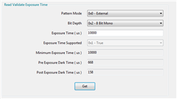
- Scroll down on the right and find Read Validate Exposure time block (see below)
- Select your desired Pattern Mode, Bit Depth, and exposure time and then select Get
- If the exposure time is supported, the GUI will return 0x1 - True under Exposure Time Supported. Otherwise it will return 0x0 - False
- If the exposure time is supported the minimum Pre Exposure Dark Time (us) and Post Exposure Dark Time (us) will both be returned.
What if I want to quickly stream 2D patterns?
- You can use external pattern streaming mode. This mode makes use of the parallel input on the DLPC347x controllers. On the EVMs this mode can be used by hooking up a video source to the HDMI input (additional circuitry on the EVMs converts this signal to the parallel input on the DLPC347x controller). In this mode each the patterns are encoded into the bitplanes.
What are the supported timings for external pattern streaming mode?
- For a desired exposure time, find the proper sequence number (using the exposure time range) in the below table. Then calculate the minimum pre-exposure dark time and post-exposure dark time using the same equations as for internal pattern streaming above.
Please view the Sequence Timings for DLPC347x Light Control Platform E2E post for the latest table of timings.
What if I want to display 2D patterns that are stored in flash?
- One can utilize splash pattern mode. This mode is primarily intended for applications where very high speed pattern display is not needed (such as 3D printing). Note there will be a load time penalty when switching between different splash patterns.
What are the supported timings for splash pattern mode?
- For a desired exposure time, find the proper sequence number (using the exposure time range) in the below table. Then calculate the minimum pre-exposure dark time and post-exposure dark time using the same equations as for internal pattern streaming above.
- Note: The maximum pattern period (pre-exposure + exposure + post-exposure) cannot exceed 2184us for 1-bit patterns and 17476us for 8-bit patterns
Please view the Sequence Timings for DLPC347x Light Control Platform E2E post for the latest table of timings.
Can I design a system using monochrome mode (i.e. just 1 LED)?
- Yes! This is may be a useful case when building a 3D printer (where perhaps only a 405nm LED would be needed) or a 3D scanner where the camera only needs to capture the light output of one color (or maybe even an infrared LED). The non-connected LEDs must be disabled or the PMIC will shut down. This is applicable for all modes where LEDs are enabled (i.e. display and Light Control).” LEDs can be disabled using the Write RGB LED Enable command.


