This thread has been locked.

If you have a related question, please click the "Ask a related question" button in the top right corner. The newly created question will be automatically linked to this question.

TCAN4550: cannot send data

Part Number: TCAN4550

Hi Team,

Intention: A standard CAN 2.0B port is extended using the TCAN4550. It is planned to communicate with CAN 2.0B devices. To avoid introducing additional problems, the customer expect to debug the send/receive of demo’s standard frame before debugging other functions.

For the filter, the mask registers are initialized to 0, which means all messages are accepted. 

Issue: The data frame in demo of the TCAN4550 cannot be transmitted to the CAN bus. 

Step:

1) Port the MSP430-based TCAN4550 demo to customer own M3 processor. The M3 and TCAN4550 read and write data are good(device ID will return the device ID normally), indicating that debug based on migration needs can function.

2) The application layer is basically unchanged. However, when initializing the standard ID filter configuration, it is always inconsistent with the written value, causing configuration errors as shown in the following figure: 

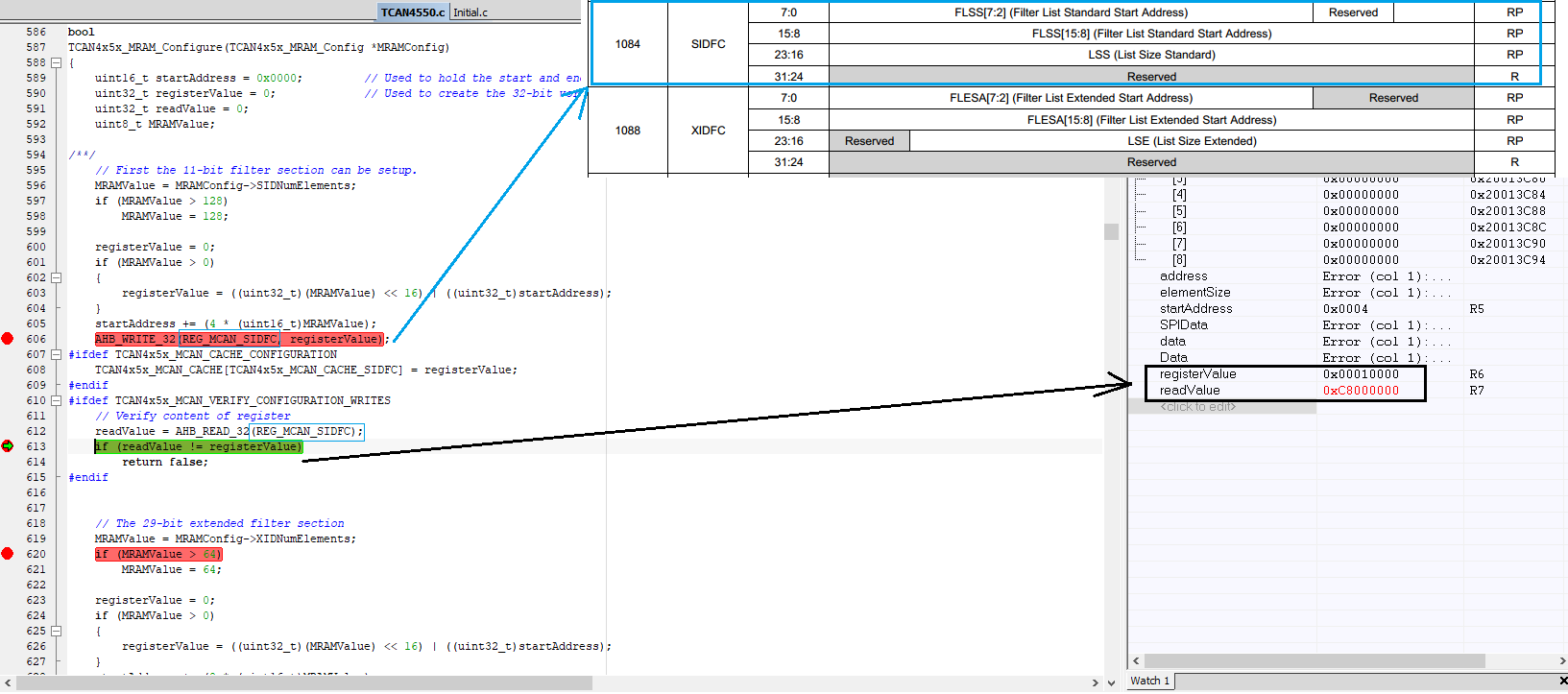
Because the value written by SIDFC does not match the return value, it exits directly, resulting in incorrect data in TCAN4x5x_MCAN_CACHEITCAN. Data exceptions in the cache are checked for subsequent writes and cannot be written directly. The application layer basically follows the application layer logic of demo and is unchanged.

The customer would like to know what's the possible cause of the write and read inconsistency issue.

3) If the can FD initialization in demo is used as can 2.0B, is it possible to properly communicate with can 2.0B devices?

Could you help check this case? Thanks.

Best Regards,

Cherry

  • Hi Cherry,

    1) Port the MSP430-based TCAN4550 demo to customer own M3 processor. The M3 and TCAN4550 read and write data are good(device ID will return the device ID normally), indicating that debug based on migration needs can function.

    I am assuming the "read and write data" you are referring to is SPI data and not CAN message data correct?  If so, I'm not sure that it can be said that the communication is entirely good.  The read value of "0xC8000000" that is highlighted in the picture shows that the SPI Error (SPIERR) bit is set which is bit 3 of register 0x0820.  Each SPI read/write transaction will return the "Status Byte" or bits 7:0 of register 0x0820 at the start of the SPI transaction.  The SPIERR bit will be set when any of the bits 0x000C[30:16] are set.

    Can you share the value of register 0x000C and possibly scope or logic analyzer captures of the SPI signals so that we can determine what type of SPI error is occurring?

    The SIDFC incorrect value may be due to the SPI errors.  But the SIDFC register is also a write protected register and the INIT and CCE bits of register 0x1018 need to be both set to 1 in order for the SIDFC register to be updated to a new value.  Can you verify the value of register 0x1018 has both bits 0 and 1 set to "1" while you are trying to write to the SIDFC register with your new value?  If the INIT and CCE bits are not both set to "1" the device will not change the SIDFC register value when you write to it.

    3) If the can FD initialization in demo is used as can 2.0B, is it possible to properly communicate with can 2.0B devices?

    Yes, the device can communicate with 2.0B devices.

    Regards,

    Jonathan