Other Parts Discussed in Thread: ISO1042, ISOW7841, ISOW1044, ISOW7741, ISO7841
Dear Sirs,
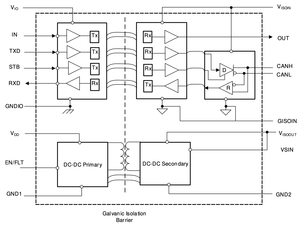
I am looking for information about the Hardware Implementation of the Signals´ Transmission in the ISO1044 Transceiver.
I will list my questions after some key points, however the final question reduces to:
in a Digital Isolator, when is a Capacitive Isolation Technology used instead of a Magnetic Isolation Technology?
Referring to SLLSFB0A ISO1044 Datasheet (“This device” = the ISO1044B = Device Marking for the ISO1044):
“This device uses a silicon dioxide (SiO2) insulation barrier”.
Referring to SLLA564 §2:
“For digital isolators, the primary insulation is provided by thin-film layers of silicon dioxide (SiO2) or polymer-based dielectric applied across a high voltage capacitor or transformer.”
Referring to the video “Reinforced Isolation and Power: An Integration Story”
The Isolation Technologies available are Optical, Capacitive and Magnetic, however choosing the Capacitive Isolation Technology does not exclude the use of SiO2 for Magnetic Technology (as per SLLA564 §2).
Referring to SLLA484 (April 2020) Page 2:
“Isolation Reliability: ISO1044 and ISO1042 are based on TI’s SiO2 based capacitive isolation technology.”
Referring to SSZY028 (2017) Page 2:
“This technical brief discusses in detail TI’s capacitor based reinforced isolation for signaling.”
“High voltage (HV) isolation is achieved using two thick SiO2 capacitors in series – one on each side of the isolation barrier.”
Especially Figure 2 of SSZY028 shows how the connection between Transmitter and Receiver is realized using 2 High Voltage Capacitors connected in series, therefore doubling their isolation capabilities.
Questions:
1. No Micro-Transformer like in the ISOW7841 (refer to SLLA368C Abstract) is used in the ISO1044.
- Is this correct?
2. It is correct to assume the following for ISO1044 Transceivers?
- there are only Capacitances and SiO2 to implement the Isolation
- the Signals´ Transmission relies on Displacement Currents only, with a Maximum Pulse Frequency related to the Rise and Fall Times of the Signals itself
- there is no modulation of the Signals with a Micro-Transformer an a Carrier in the MHz Range
3. If the answer to Question 2 is "YES": why the same technique is not used in ISOW7841-like devices?
4. If the answer to Question 2 is "NO", given the 3 Channels of an ISO1044 Transceiver:
- Channel 1 = for the Single Ended Signal “TXD” with return current on Ground 1
- Channel 2 = for the Single Ended Signal “RXD” with return current on Ground 1
- Channel 3 = for the Differential Signals at the Pins "CANH" & "CANL" with, for example, Forward Current on "CANH" and Return Current on "CANL"
- How are the Two separate Single Ended Signals “TXD” and “RXD” of the 8-Pin ISO1044 transformed and transmitted as Differential Signals "CANH" & "CANL"?
5. Why §11.2 of SLLSFB0A ISO1044 Datasheet or §4.2 of SLLA284 suggest to do not use Copper directly under the ISO1044 Transceiver while a Digital Isolator like the ISOW7841 can benefit from an Integrate Stitching Capacitance?
- Even though with that Stack-Up suggestion the distance of 40 mils is just too much to have a useful Integrated Capacitor it is always better than a Discrete Capacitor Solution, which cannot be effective over 200 MHz due to parasitic effects.
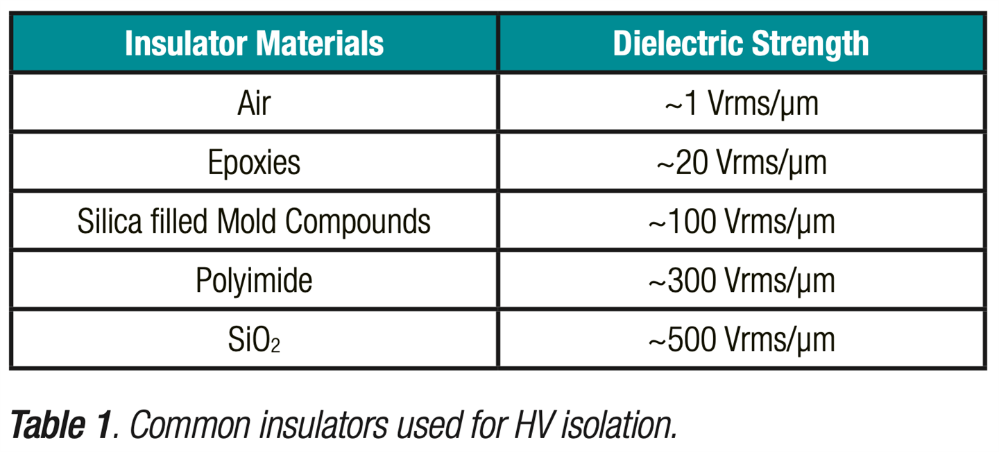
- Isolation Requirements would in any case be met, thanks to the 20kV/mm Dielectric Strength of the FR4 Material (SLLA368C Page 7).
6. Are there further EMC Recommendations to reduce the Emissions of the ISO1044 (8-Pins) CAN Transceiver other than the ones present in the already above mentioned Literature Documents?
Thanks a lot in advance.
Best Regards,
MB