The TI E2E™ design support forums will undergo maintenance from July 11 to July 13. If you need design support during this time, open a new support request with our customer support center.
A related question is a question created from another question. When the related question is created, it will be automatically linked to the original question.
If you have a related question, please click the "Ask a related question" button in the top right corner. The newly created question will be automatically linked to this question.
[FAQ] How do you set current limits and voltage thresholds in your system using digital input modules?
The ISO1211 and ISO1212 isolated digital input modules must be used with a RSENSE resistor, RTHR resistor, and CIN capacitor. RSENSE in the diagram below limits the current drawn from the field input.
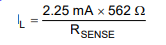
Setting a current limit minimizes power dissipation in the system. The ISO121x devices can be set to Type 1, Type 2, and Type 3 operation. A 562 Ω resistor as RSENSE will set the current limit to 2.25mA, recommended for Type 1 and Type 3 operation. A 200 Ω resistor will set the current limit to 6 mA, recommended for Type 2 operation. The equation to calculate current limit from RSENSE resistance is below.
The resistor RTHR is used to set voltage thresholds (VIH and VIL) as well as limit surge current given by equations below. A value of 1 kΩ is recommended for RTHR in Type 3 systems (maximum threshold voltage required is 11 V). A value of 2.5 kΩ is recommended for RTHR in Type 1 systems (maximum threshold voltage required is 15 V) and a value of 330 Ω is recommended for RTHR in Type 2 systems. Other RTHR values to set voltage thresholds can be calculated by linear interpolation. Please refer to our online datasheet to learn more about increasing maximum voltage supported past 60V. While these resistors are required to set the current limits and voltage thresholds, CIN is needed to filter input noise/EMC transients.