This thread has been locked.

If you have a related question, please click the "Ask a related question" button in the top right corner. The newly created question will be automatically linked to this question.

TMS570LS1224: using can bootloader not jump from bootloader to application code

Part Number: TMS570LS1224
Other Parts Discussed in Thread: TMS570LC4357, TMS570LS1227, UNIFLASH

Hi All,

I am using TI TMS570LS1224 controller for the CAN based bootloader.

In this i have written the bootloader code and flashing it through debugger flashing is fine.

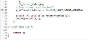
After that i am using INCA tool to flash the .Hex file and .A2L file of application code, the flashing of the code through INCA is also working but once i get an power on reset then the code should jump from bootloader to application. but this step is not happening in my case so please connect someone who is having and expertise in the bootloader..

I am using the application start address 0x20000 and i have checked in memory too having the same values whatever .hex file is having

Thanks in advanced.

Regards,

Shriram Madhavai

  • Hi Shriram,

    Started working on your issue and will provide an update soon.

    --

    Thanks & regards,
    Jagadish.

  • Hi Shriram,

    In this i have written the bootloader

    Looks like you written your own customized bootloader, so it is difficult to find out the root cause until we got complete project of yours.

    So, can you please refer our example CAN bootloader project for TMS570LS1224?

    CAN_Boot_Loader.zip

    --

    Thanks & regards,

    Jagadish.

  • Hi jagadish,

    Please find the attached application code which i am trying to flash using inca tool on top of bootloader.

    check and revert.

    Thanks and Regards,

    Shriram Madhavai

  • Hi Shriram,

    I can't able to access the code.

    Can you please zip the project and attach directly to the e2e?

    Or else even you can share to me via private message as well?

    --

    Thanks & regards,
    Jagadish.

  • Hi Shriram,

    Thanks for providing code, i will go through it and try to provide an update as soon as possible.

    --

    Thanks & regards,
    Jagadish.

  • Hi Jagadish,

    I used the CAN_Boot_Loader example to get the jump to the application function.


    UART_putString(UART, "\r Jump to application... ");
    g_ulTransferAddress = (uint32_t)APP_START_ADDRESS;
    ((void (*)(void))g_ulTransferAddress)();

    This is the function that I used. But I could not jump to the application. Is there anything other do I need to perform?

  • Hi Jagadish,

    One update from my side i am able to jump to application code but not working anything in application.

    i have used the bootloader code whichever you have shared CAN Bootloader.

    Now i have replicated same in my bootloader code too and it is jumping to the application code.

    Is there anything i am missing in startup file to add in the startup fille i am using whatever is there in LED blinky code.

    In application i am blinking LED and it is not working please check on that part .

    Is there i have to change in startup of linker file which i have shared.

    Thanks and Regards,

    Shriram Madhavai

  • Hello Shriram,

    This may be because of the application offset address. It must align to a page boundary. What is your current application offset address?

  • Hi Rahul,

    In my bootloader code the application start address is 0x20000 and the application offset address i may not have much idea about it or i did't understand it correctly or there might have different convention for the same,

    So please can you tell me that where to see it or how to check.

    Thanks and Regards,

    Shriram Madhavai

  • Hi Shriram, 

    You can find your flash memory partition details in the .cmd file of your application project. The offset should be a multiple of 1024 (in decimal) in order to be aligned at the page boundary.

    If you're providing the application start address as 0x20000 in your bootloader code. The same address should be the offset address of your application.

  • Please find the application .cmd file and having 20000 is the address for vector too.


    /* Linker Settings */

    --retain="*(.intvecs)"
    --retain="*(.var)"

    /* USER CODE BEGIN (1) */
    /* USER CODE END */

    /*----------------------------------------------------------------------------*/
    /* Memory Map */

    MEMORY
    {
    /*Use below addresses after Bootloader Implementation*/
    VECTORS (X) : origin=0x00020000 length=0x00000020
    FLASH_API (RX) : origin=0x00020020 length=0x000037FF
    FLASH0 (RX) : origin=0x00024000 length=0x0011BFFF
    FLASH1 (RX) : origin=0x00018000 length=0x00001000 //4kB= 0x1000
    STACKS (RW) : origin=0x08000000 length=0x000031FF
    RAM (RW) : origin=0x08003200 length=0x00027DFF
    RAM1 (RW) : origin=0x0802EFFF length=0x00001000 // 4kB = 0x1000

    /* Section Configuration */

    SECTIONS
    {
    .intvecs : {} > VECTORS
    .text : {} > FLASH0
    .const : {} > FLASH0
    .cinit : {} > FLASH0
    .pinit : {} > FLASH0
    .bss : {} > RAM
    .data : {} > RAM
    .sysmem : {} > RAM
    .costvltile : {} > FLASH1

    FEE_TEXT_SECTION : {} > FLASH0 //for internal FEE
    FEE_CONST_SECTION : {} > FLASH0 //for internal FEE
    FEE_DATA_SECTION : {} > RAM //for internal FEE
    .constvltile : load = FLASH1, run = RAM1

    /* USER CODE BEGIN (4) */
    flashAPI :
    {
    //..\Debug\source\BMS_CCP.obj(.text) /*in order to use this linker file in CCS, uncomment this line; but for matlab TSP comment out this line*/

    //C:\TML_WBMS_TSP\CCS_WBMS_Code\source\BMS_CCP.obj(.text) //Change according to the project location
    //..\TI_WBMSProject\BMS_CCP.obj(.text) //Change according to the project location
    --library= F021_API_CortexR4_BE_V3D16.lib < FlashStateMachine.IssueFsmCommand.obj
    FlashStateMachine.SetActiveBank.obj
    FlashStateMachine.InitializeFlashBanks.obj
    FlashStateMachine.EnableMainSectors.obj
    FlashStateMachine.IssueFsmCommand.obj
    FlashStateMachine.ScaleFclk.obj
    Init.obj
    Utilities.CalculateEcc.obj
    Utilities.WaitDelay.obj
    Utilities.CalculateFletcher.obj
    Read.MarginByByte.obj
    Read.Common.obj
    Read.FlushPipeline.obj
    Read.WdService.obj
    Async.WithAddress.obj
    Program.obj > (.text)
    } load = FLASH_API, run = RAM, LOAD_START(api_load), RUN_START(api_run), SIZE(api_size)

    thanks and Regards,

    Shriram MAdhavai

  • Hi Shriram,

    I don't have any board with "TMS570LS1227" controller, so i did a small testing on TMS570LC4357 HDK board. It worked for me so please try to follow the same steps on your side and see the result.

    1. I don't have even NI-CAN adapter to send application through PC via CAN, so i just downloaded one LED blinky example directly to the controller.

    For this purpose i used UniFlash tool, and my application starting address is 0x20020, so i gave same load address to the UniFlash. Here i set erase option as entire flash

    So, first i programmed application and then i performed below step

    2. Actually in bootloader application we will check whether the signature(0x5A5A5A5A) present or not at APP_STATUS_ADDRESS address

    If this signature present, then only we consider as application present in the flash

    For my testing as i am not programming any application directly through CAN so i just enabled below line in the code


    This will make bootloader to consider the application already exists.

    And i also changed application start address to the 0x20020

    After doing above two changes i also make sure that erase option to be "necessary sectors only", because programming my bootloader should not erase the already existing application right.

    After doing that i just loaded my bootloader into the flash and i can see the LED blinking 

    and also i can see the below data in the UART

    So, please follow above steps and see the result on your end also.

    --

    Thanks & regards,
    Jagadish.

  • Hi Jagadish,

    First i have some queries ,

    1. What is the vector address for your application and Bootloader?

    2. Why the Application start address is 0x20020 why not 0x20000?

    3. I have did the same steps whatever you are doing so i am getting 

    now i will give you the steps whatever i have performed..

    1- i have built with the application code with below linker file.

    After that i have tried the flashing the application code through uniflash with below settings.

    the erase setting for this now 

    after that i have flashed it and i can see the symbols in the memory sectors.

    after that i have flashed the bootloader code with 

    and the flag whatever is there that i have bypassed and directly jumped to the application.

    and the start address of application is.

    for just reference i am blinking the LED in bootloader also and Application also

    So in bootloader LED is blinking but once it jumped to application then it is not working.

    This are the steps whatever you have shared..

    After that one changes from my side too for other way of flashing using INCA tool for TMS570LS1224.

    if i flashed the code using INCA tool it is flashing but i am not able to see any changes in the low level registers for GPIO pin and other peripherals.

    Only here i can see the Interrupt is working and code flow is also i am able to see using CCS by connecting target configurations.

    Here are some queries - Is there any way that the controller will goes in lock after flashing through INCA tool.

    - OR one thing is that i am using same Startup file in bootloader and application also 

    So is there any changes in both startup file or is controller is going to the privileged mode and not allowing to modify the registers.

     Thanks and Regards,

    Shriram Madhavai

  • Hi Shriram,

    1. What is the vector address for your application and Bootloader?

    Application: 0x00020020
    Bootloader: 0x00000020

    Bootloader code start at 0x00000020 because interrupt vectors will present from 0x00000000

    2. Why the Application start address is 0x20020 why not 0x20000?

    Actually, in bootloader code they are using some 0x20 bytes of location to store the signature(which will helpful to find out whether the application present or not). This signature will be written only after writing complete application into the flash using bootloader.

    You can see the above highlighted line right; there they are programming the signature after the complete application written to the flash using bootloader code.

    --

    Thanks & regards,
    Jagadish.

  • Hi Jagadish,

    Can you please share the application and bootloader .cmd file so i can do the same changes in my code too.

    Thanks and Regards,

    Shriram Madhavai

  • Hi Jagadish,

    The application is jump from bootloader to application and it is not working previously but after changing the clock function MapClock() in system.c file it starts working and flashing correctly.

    Thanks and Regards,

    Shriram Madhavai