This thread has been locked.

If you have a related question, please click the "Ask a related question" button in the top right corner. The newly created question will be automatically linked to this question.

TMDS243EVM: PCIE: RC read EP Bar info stuck. 243EVM+Intel FPGA

Part Number: TMDS243EVM
Other Parts Discussed in Thread: SYSCONFIG

Tool/software:

Hi Ti Expert,

            (FPGA kit): https://www.arrow.com/en/products/dk-dev-10cx220-a/intel?q=DK-DEV-10CX220-A

             I try to use this FPGA kit as EP and 234EVM as RC.

             The EP has two bar, bar0 and bar1.

             I can read the statue_cmd from EP, but can't configure bar for EP. The following are the code of mine.

             It always stuck in : type0BarIdx.idx reading in Pcie_cfgBar().

             My SDK version:mcu_plus_sdk_am243x_09_00_00_35

            Pleas help me with that!

Thanks 

Chunyang 

int32_t pcie_fpga_ep_test(Pcie_Handle handle)
{
int32_t status = SystemP_SUCCESS;
Pcie_Registers getRegs;
Pcie_StatusCmdReg statusCmd;

memset (&getRegs, 0, sizeof(getRegs));
getRegs.statusCmd = &statusCmd;

status = Pcie_readRegs (handle, PCIE_LOCATION_REMOTE, &getRegs);

if (SystemP_SUCCESS != status)
{
DebugP_log("FPGA state read test fail\r\n");
}
else
{
DebugP_log("FPGA state read test done\r\n");
}

return status;
}

int32_t pcie_fpga_ep_bar1_cfg(Pcie_Handle handle)
{
int32_t status = SystemP_SUCCESS;
Pcie_BarCfg barCfg;

barCfg.location = PCIE_LOCATION_REMOTE;
barCfg.mode = PCIE_EP_MODE;
barCfg.base = 0x70000000;
barCfg.prefetch = PCIE_BAR_NON_PREF;
barCfg.type = PCIE_BAR_TYPE32;
barCfg.memSpace = PCIE_BAR_MEM_MEM;
barCfg.idx = 0;//1;

status = Pcie_cfgBar (handle, &barCfg);

//DebugP_assert(SystemP_SUCCESS == status);

if (SystemP_SUCCESS != status)
{
DebugP_log("FPGA Bar1 configure fail\r\n");
}
else
{
DebugP_log("FPGA Bar1 configure done\r\n");
}

return status;
}

  • Hi ,

    Thanks for your query.

    I will check on this and get back to you.

    Regards

    Ashwani

  • Hello ,

    that API is not suitable for accessing a "generic" EP, as it mostly assumes that there's a AM24x/AM64x connected to another AM24x/AM64x.

    The cfgBar is actually not meant to configure base address, but to configure the attributes (size and type, i.e. I/O, MEM, 32/64 bit, prefetchable) of a BAR. When you call that for PCIE_LOCATION_REMOTE, the driver assumes that there's another AM64x on the other end, and attempts to read/write the registers that determine what that AM64x's BARs look like.

    You could try using Pcie_read/writeRegs to read/write type0Bar32bitIdx. That should get you get you the actual content of the BAR registers of your EP.

    Since Pcie_read/writeRegs most likely doesn't support all the config space registers you're going to want to read/write, you might be better off directly accessing the config space mapping and implementing the accessor functions yourself. I'll see if I can get you an example later today.

    Regards,

    Dominic

  • Hi Dominic,

    Thanks for your supporting.

    Now, my EP-Bar-Cfg function as the following code shows.

    I have no idea whether it works.

    int32_t pcie_fpga_ep_bar1_cfg2(Pcie_Handle handle)
    {
    int32_t status = SystemP_SUCCESS;
    Pcie_Registers setRegs;
    Pcie_Type0Bar32bitIdx type0Bar32bitIdx;

    memset (&setRegs, 0, sizeof(setRegs));
    type0Bar32bitIdx.reg.reg32 = 0x70000000;
    type0Bar32bitIdx.idx = 1;
    setRegs.type0Bar32bitIdx = &type0Bar32bitIdx;

    status = Pcie_writeRegs(handle, PCIE_LOCATION_REMOTE, &setRegs);


    if (SystemP_SUCCESS != status)
    {
    DebugP_log("FPGA Bar1 configure fail\r\n");
    }
    else
    {
    DebugP_log("FPGA Bar1 configure done\r\n");
    }

    return status;
    }

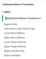
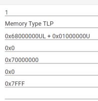
    My RC's outbound are like the following.

    I try to withe the EP's Bar1 using the following code, but it did not work.

    {

    void *transBufAddr = (void *)(CONFIG_PCIE0_OB_REGION0_LOWER);

    memcpy(transBufAddr, src_buf, BUF_SIZE * sizeof(uint32_t));

    CacheP_wbInv(transBufAddr, sizeof(uint32_t) * BUF_SIZE, CacheP_TYPE_ALL);

    }

    looking forward your further help!

    Thanks

    Chunyang 

  • Hello Chunyang,

    did you enable your EP to respond to memory requests by setting the appropriate bit in the command register? By default that should be disabled.

    It would also be good to verify the write to the BAR register succeeded by reading back the register.

    Regards,

    Dominic

  • Hi Rath,

       Did you mean this statusCmd register?

       I have done statusCmd's setting like the following, and I can read out these value as I wrote.


    But, I read out the type0Bar32bitIdx's contents just 0,  however I have wrote 0x70000000 to type0Bar32bitIdx.reg.reg32 = 0x70000000.

    The following are the writing and reading functions.

    int32_t pcie_fpga_ep_bar1_cfg2(Pcie_Handle handle)
    {
    int32_t status = SystemP_SUCCESS;
    Pcie_Registers setRegs;
    Pcie_Type0Bar32bitIdx type0Bar32bitIdx;

    memset (&setRegs, 0, sizeof(setRegs));
    type0Bar32bitIdx.reg.reg32 = 0x70000000;
    type0Bar32bitIdx.idx = 1;
    setRegs.type0Bar32bitIdx = &type0Bar32bitIdx;

    status = Pcie_writeRegs(handle, PCIE_LOCATION_REMOTE, &setRegs);


    if (SystemP_SUCCESS != status)
    {
    DebugP_log("FPGA Bar1 configure fail\r\n");
    }
    else
    {
    DebugP_log("FPGA Bar1 configure done\r\n");
    }

    return status;
    }

    ----------------------

    int32_t pcie_fpga_ep_bar1_cfg2_read(Pcie_Handle handle)
    {
    int32_t status = SystemP_SUCCESS;
    Pcie_Registers getRegs;
    Pcie_Type0Bar32bitIdx type0Bar32bitIdx;

    memset (&getRegs, 0, sizeof(getRegs));
    memset (&type0Bar32bitIdx, 0, sizeof(type0Bar32bitIdx));

    getRegs.type0Bar32bitIdx = &type0Bar32bitIdx;
    status = Pcie_readRegs(handle, PCIE_LOCATION_REMOTE, &getRegs);


    if (SystemP_SUCCESS != status)
    {
    DebugP_log("FPGA Bar1 configure read fail\r\n");
    }
    else
    {
    DebugP_log("FPGA Bar1 configure read done\r\n");
    }

    return status;
    }
    Can you tell me, why I cannot write or read the register: type0Bar32bitIdx?

    Thanks 

    Chunyang 

  • Hello Chunyang,

    id you mean this statusCmd register?

       I have done statusCmd's setting like the following, and I can read out these value as I wrote.

    it seems like you wanted to include a screenshot, but that's not being displayed.

    Bit 1 "Memory Space" needs to be set to enable the EP to respond to BAR memory accesses.

    But, I read out the type0Bar32bitIdx's contents just 0,  however I have wrote 0x70000000 to type0Bar32bitIdx.reg.reg32 = 0x70000000.

    I believe there's a mistake in your code to read back the Bar1 register. You're not setting type0Bar32bitIdx->idx to '1', so you're reading back whatever's configured for Bar0. When reading you still need to tell the driver which BAR you want to read via the ->idx field. As you're zeroing that structure before, you're telling it to read Bar0.

    Best Regards,

    Dominic

  • Hi Dominic,

       1  The screenshot in my previous post is the following code, which I want to say that the Bus and Mem access are enabled.

    memset (&setRegs, 0, sizeof(setRegs));
    statusCmd.memSp = 1;
    statusCmd.busMs = 1;
    statusCmd.resp = 1;
    statusCmd.serrEn =1;
    setRegs.statusCmd = &statusCmd;

    status = Pcie_writeRegs(handle, PCIE_LOCATION_REMOTE, &setRegs);

    2 Following your guide, now I can read out type0Bar32bitIdx.reg.reg32 = 0x70000000.

    3 My outbound setting are like the following picture, I don't know whether it could be seen by you. It's the original setting from //pcie_buf_transfer_rc 


       4 After setting statusCmd and type0Bar32bitIdx, I try to write Bar1 of the EP, by the following code, but it seems it didn't work.

    {

    void *transBufAddr = (void *)(CONFIG_PCIE0_OB_REGION0_LOWER);

    memcpy(transBufAddr, src_buf, BUF_SIZE * sizeof(uint32_t));

    CacheP_wbInv(transBufAddr, sizeof(uint32_t) * BUF_SIZE, CacheP_TYPE_ALL);

    }

    Is there anything wrong? Please help me with it.

    Thank

    Chunyang 

  • Hi Dominic,

        For your information.

        Instead the memcpy() in my previous post I used the following function to write the Bar1 of EP, following so other example.

        The pcieBase is 0x68000000, when write 0xFFFFFFFF to this address, the debug crashed.

    int32_t pcie_fpga_get_memSpace(Pcie_Handle handle)
    {
    void *pcieBase;

    if(Pcie_getMemSpaceRange(handle, &pcieBase, NULL) != SystemP_SUCCESS)
    {
    DebugP_log("get Men Space base fail\r\n");
    }

    *((volatile uint32_t *)pcieBase) = 0xFFFFFFFF;
    *((volatile uint32_t *)pcieBase + 1) = 0xFFFFFFFF;
    *((volatile uint32_t *)pcieBase + 2) = 0xFFFFFFFF;
    *((volatile uint32_t *)pcieBase + 3) = 0xFFFFFFFF;
    *((volatile uint32_t *)pcieBase + 4) = 0xFFFFFFFF;
    *((volatile uint32_t *)pcieBase + 5) = 0xFFFFFFFF;

    return 0;
    }

  • Hello Chunyang,

    in your previous post you're showing that the lower base address is 0x68000000 + 0x01000000, i.e. 0x69000000. If pcieBase is just 0x68000000 then I wouldn't expect that to work.

    You said:

       4 After setting statusCmd and type0Bar32bitIdx, I try to write Bar1 of the EP, by the following code, but it seems it didn't work.

    How do you determine "didn't work"? The examples, e.g. pcie_msi_irq_rc use similar code, and they work (although the CacheP_wbInv shouldn't be necessary, because the 0x68... range is mapped as strongly ordered memory, and therefore doesn't cache).

    -> What exactly "didn't work"? Does it crash like the second post with pcieBase? Or something else?
    -> What kind of functionality did you implement in your FPGA behind Bar1?

    Regards,

    Dominic

  • Hi Dominic,

     To answer your questions.    

    -> What exactly "didn't work"? Does it crash like the second post with pcieBase? Or something else?
    -> What kind of functionality did you implement in your FPGA behind Bar1?

    I meant the EP--FPGA did not response as expected, no crash here. The FPGA gay made the first byte of Bar1 to turn on a LED.

    It's been proven by mounting the FPGA card to a PC. The LED can be turned on by writing the first byte of Bar1 through PC's windows app.

    -----------------------------------------------------------------

    I want to consult the followings.

    1 My setting of OB is: base address = 0x68000000 + 0x01000000, while I got the pcieBase from pcie_fpga_get_memSpace() is 0x68000000. Is it wrong?

    2 What is the proper way to access data Mem Bar1 of EP? memecpy() or  *((volatile uint32_t *)pcieBase) = 0xFFFFFFFF?

    3 Why my debug crashed when use *((volatile uint32_t *)pcieBase) = 0xFFFFFFFF way to write 0x68000000 or 0x68000000 + 1 or 0x68000000 + 0x01000000?

  • Hello Chunyang,

    I meant the EP--FPGA did not response as expected, no crash here. The FPGA gay made the first byte of Bar1 to turn on a LED.

    It's been proven by mounting the FPGA card to a PC. The LED can be turned on by writing the first byte of Bar1 through PC's windows app.

    okay, understood.

    1 My setting of OB is: base address = 0x68000000 + 0x01000000, while I got the pcieBase from pcie_fpga_get_memSpace() is 0x68000000. Is it wrong?

    I'm not sure about the PCIe driver APIs for RC, e.g. which function should be used for what purpose... I'd use the CONFIG_PCIE0_OB_REGION<n>_LOWER generated for the outbound mappings from SysConfig.

    2 What is the proper way to access data Mem Bar1 of EP? memecpy() or  *((volatile uint32_t *)pcieBase) = 0xFFFFFFFF?

    Both should work. With memcpy() the compiler might make optimizations that are only valid for "normal memory" (i.e. cacheable, no strong ordering). Whether that is possible depends on how you configure the 0x68000000 region in the MPU, and it depends on the memcpy() implementation. For "registers" behind those BARs I'd make sure the MPU maps the memory as strongly ordered (maybe device, if you know what you're doing) and use *(volatile uint32_t*).

    3 Why my debug crashed when use *((volatile uint32_t *)pcieBase) = 0xFFFFFFFF way to write 0x68000000 or 0x68000000 + 1 or 0x68000000 + 0x01000000?

    Is it crashing for EACH of those addresses?

    I can understand why it crashes for an address range that is not mapped via an outbound memory region, but CONFIG_PCIE0_OB_REGION1_LOWER should work.

    Just to be sure:

    CONFIG_PCIE0_OB_REGION1_LOWER is 0x69000000, and it doesn't crash with memcpy, but it crashes with volatile uint32_t*?

    Regards,

    Dominic

  • Hello Chunyang,

    one more thought:

    Is your FPGA using 32-bit or 64-bit BARs?

    Regards,

    Dominic

  • Hi Dominic,

        With your help, now I could read and write EP's memory. 

        The following code can work.

      uint32_t * test = (uint32_t *)(0x69000000U + 0x4000); // 0x4000 is the offset in FPGA side

      uint32_t data_buff[64]; // for read test

      for(i = 0; i < 64; i++)
      {
            *test++ = i;       // write the 64 address with 0, 1, 2, 3...63
       }

      memcpy(data_buff, test-63, 64 * sizeof(uint32_t)); // read back the 0,1,2...63. it is all right

    ------------------------------------------------------------------————————————————————————

    But the following code cannot work.

    uint32_t * test = (uint32_t *)(0x69000000U + 0X00004000);

    uint32_t data_buff[64];
    uint32_t data_buff2[64];

    for(i = 0; i < 64; i++)
    {
    data_buff[i] = i;
    }

    memcpy(test, data_buff, 64 * sizeof(uint32_t));  // write EP
    memcpy(data_buff2, test, 64 * sizeof(uint32_t)); // read back, there all "0"!

    I insert CacheP_wbInv(test, sizeof(uint32_t) * 64, CacheP_TYPE_ALL)  between this two memcpy(), and I also and some print() for delay purpose. 

    But the read back data_buff2 always all "0".

    My questions is how can I use memcpy() to write EP' memory properly?

    Or should I just use "*test++ = i" way to write?

    Thanks 

    Chunyang 

  • Hello Chunyang,

    glad you got read/write basically working.

    Are you running a debug build or a release build? With release you could be running into problems with the compiler optimizing your code. I don't think that's currently your problem, but I wanted to make sure you're aware of that possibility. In your test code the optimizer could just optimize away any accesses to the FPGA.

    It seems that reading back from your FPGA with memcpy works just fine, just writing to the FPGA appears to be a problem. It would be good if you could verify that by using the same code, and just replacing the memcpy() that writes to the FPGA with a for(...)*ptr = *dst loop, and leave everything else the same.

    If it is really the memcpy then maybe the FPGA is having a problem with the PCIe transactions triggered by the memcpy vs. the 32-bit pointer access. The memcpy could be triggering larger bursts, and maybe that's something your FPGA can't handle?

    To verify that, you could try using a uint64_t pointer to write to the FPGA. memcpy could of course be using even longer bursts, but that's more difficult to reliably trigger. If writing using a uint64_t doesn't work either you'd have to look at your FPGA implementation.

    Regarding the use of CacheP: You need to check how you're configuring the MPU. Normally I'd expect the 0x68000000 range to be configured as strongly-ordered. In that case you don't need CacheP_wbInv.

    Regards,

    Dominic

  • Hi Dominic,

       I am running a debug build by now. When using release I would disable the optimizing.
       Following your guidance, I used the same code only replace memcpy() with *ptr = *dst.
       I came to the following results by using memcpy() to write EP's fpga memory.

    Write fpga with memcpy() Readback Check 
    8×32bit, all are 0xaffffff5 all are 0xaffffff5
    16×32bit, all are 0xaffffff5 all are 0xaffffff5
    17×32bit, all are 0xaffffff5 all are 0xaf000000
    32×32bit, all are 0xaffffff5 all are 0xaf000000
    64×32bit, all are 0xaffffff5 all are 0x00000000

      When I try to 8 or 16 32bit data to fpga using memcpy, the readback is what I wrote. There was something wrong when the number of data(32bit) is bigger than 16.

       What is your comment about this problem?

       The Maximum payload size(MPS) of FPGA side is 128 Bytes.

        Is there anything to with MPS or Max read request size(MRRS)?

        If yes, how config MPS and MRRS for my 243EVM RC? 

    Thanks

    Chunyang 

  • For your info, this is the Device Status and Control Register of my RC.

    maxpayload = 0;

    Maximum Read Request Size--maxSz = 2

  • Hello Chunyang,

    you can configure MPS and MRRS via the PCIE0_RC_I_RC_PCIE_BASE_I_PCIE_DEV_CTRL_STATUS register at 0x0d0000c8.

    According to the TRM the MPS should already default to 128 bytes, but the MRRS would be 512. For all I know that should be ok, and the FPGA should respond with multiple completions. You could try reducing the MRRS in the above register, and see if that fixes things.

    Regards,

    Dominic

  • Hi Dominic,

          Following your previous guide, I modified the MRRS of my RC to 0.

          The following table are the values of RCB, MPS and MRRS of my RC, for current setting.

    Register

    Setting

    RCB--Read Completion Boundary

    1(default): 128B (Verified)

    MPS: (Max Payload Size),

    0(default): 128B (verified)

    MRRS(Max Read Request Size)

    0: 128B (have changed) default is 2(512)

           Are these values are proper for Sitara AM243x RC?

           I still got the same results with the above settings. I mean only less than 16*32bit  data can write and read precisely with once memcpy() operation, otherwise the read-back are wrong.

           The FPGA guy have started to check his design. Is there anything I can do to make sure Sitara MCU RC side are all right?

    Thanks

    Chunyang


  • The FPGA guy have started to check his design

    Let's see if they find some thing important.

    Is there anything I can do to make sure Sitara MCU RC side are all right?

    We are reviewing it internally and get back to you.

    Regards

    Ashwani

  • Hi Dominic,

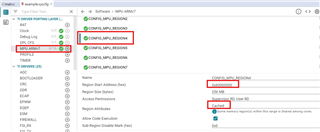
      Would you please tell me why you said here, 0x68... range is Strongly ordered?

      I check the syscfg, in Ti SDK's example, CONFIG_MPU_REGION4(from 0x60... 256MB, is Cached) 

    because the 0x68... range is mapped as strongly ordered memory, and therefore doesn't cache).

       Should I change my syscfg, to modify this REGION4 to strongly ordered?

       Strongly ordered and Cached which one is more suitable for several 32bit data PCIe accessing?

    Thanks 

    Chunyang 

  • Hi Chunyang,

    Would you please tell me why you said here, 0x68... range is Strongly ordered?

    Regarding the use of CacheP: You need to check how you're configuring the MPU. Normally I'd expect the 0x68000000 range to be configured as strongly-ordered. In that case you don't need CacheP_wbInv.

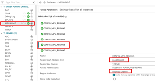
    I think Dominic is referring REGION6 as per "pcie_msi_irq_rc " example:

    While you are referring REGION4

    Regards

    Ashwani

  • Got it, perfect!

  • Hi Dominic,

           About memcpy(),

           Now, I am using memcpy() to read and write the EP(FPGA),

           I found that writing 16*32bit use 2us, reading 16*32bit use 10us.

           But reading 32*32bit use 240us

           How reading 32*32bit use so many more time than reading 16*32bit?

           Should I only read 16*32bit twice for 32*32bit reading, triple for 48*32bit reading ... for best reading speed?

           For a hint, I have not solved writing more than 16*32bit problem which will cause data damage.

    Thanks 

    Chunyang  

  • Hi Ti Expert,

                I am debugging  am243x evm RC with Intel FPGA EP. RC's OB0 matches EP's bar1.

                My trouble is that I cannot get right results if I write more than 64 bytes with memcpy().

                But, use memcpy() to read and directly write the address can work well. 

                The followings are the pictures from FPGA debug.

                The first picture is that I was writing 16* 0xf7a5ff5a to EP. There was no problem. 

                The latter is that I was writing 17* 0xf7a5ff5a to EP. Instead 17 times write, it came 17*4 times write. And 0xf7a5ff5a was split into 0xF7, 0xA5, 0xFF and 0x5A to write. It is the problem we are facing.

                My team have no idea what's the next action, please help us with that.

    Thanks 

    Chunyang 


  • Hi Chunyang,

    I will discuss this internally and get back to you.

    Not able to open this page.

    Regards

    Ashwani

  • Hi Ashwani,

        The link was for the FPGA kit, you might find the information from Intel website in the following.

    https://www.intel.com/content/www/us/en/products/details/fpga/development-kits/cyclone/10-gx.html

    Thanks for you and your team's great help, looking forward update from you.

    BR

    Chunyang 

  • Hello Chunyang,

    if I understand this correctly then you're seeing all the data in the memcpy case, too, just split across individual byte writes instead of word-writes. Can you confirm?

    Are the individual bytes (F7, A5, FF, 5A) all on avalon_mm_writedata[7:0], or are they on [7:0], [15:8], [23:16], [31:24]? That's not clear from your second picture. I'd expect these bytes to appear on different bits, but I'd also expect byte-enable signals along with that.

    Probably not a solution, but the avalon interface should support individual byte writes with byte-enable signals. If that solves the issue of "missing" data you'd probably still run into a problem due to performance.

    If so, then the next question is whether the data travels across the PCIe link like this already (individual byte writes), or if your PCIe core in the FPGA translates the PCIe transaction like this. At this point I believe somewhere within the FPGA is more likely, but I can't rule out an issue with how the AM64x sends the PCIe transaction.

    Is there a chance that your FPGA colleagues get more details about the PCIe transaction out of their FPGA debugging tool?

    It would also be interesting if you could assembly-step through the memcpy code to the point where the processor actually stores bytes to the 0x69000000 address. That would tell us what kind of burst the processor is sending to the AM64x PCIe core, and we could then try to understand what the PCIe transaction should look like.

    Regards,

    Dominic

  • Hi Dominic,

    if I understand this correctly then you're seeing all the data in the memcpy case, too, just split across individual byte writes instead of word-writes. Can you confirm?

    The following function is the code I used for the previous test. 

    If length = 16, it is all right, the result is the first picture.

    if length = 17, it is wrong, the result is the second picture.

    int32_t pcie_fpga_access_test3(Pcie_Handle han

    dle)
    {
    uint32_t * test = (uint32_t *)(0x68000000U + 0x01000000U + 0x4000U); //0x68000000U + 0x01000000U is OB base address, 0x4000U is the offset in FPGA
    const uint8_t length = 16;
    uint32_t data_buff[length]; // data to write
    uint32_t data_buff2[length]; // buffer for read
    uint8_t i;

    for(i = 0; i < length; i++)
    {
    data_buff[i] = 0x5affa5f7;
    }
    memcpy(test, data_buff, length * sizeof(uint32_t));
    memcpy(data_buff2, test, length * sizeof(uint32_t));

    return 0;
    }

    /////////////////////////////////

    It would also be interesting if you could assembly-step through the memcpy code to the point where the processor actually stores bytes to the 0x69000000 address.

    The following is the disassembly windows contents for memcpy()

    508 memcpy(test, data_buff, length * sizeof(uint32_t));
    70094898: 982A ldr r0, [r13, #0xa8]
    7009489a: A914 add r1, r13, #0x50
    7009489c: E8B1501C ldm.w r1!, {r2, r3, r4, r12, r14}
    700948a0: E8A0501C stm.w r0!, {r2, r3, r4, r12, r14}
    700948a4: E8B1501C ldm.w r1!, {r2, r3, r4, r12, r14}
    700948a8: E8A0501C stm.w r0!, {r2, r3, r4, r12, r14}
    700948ac: E891503C ldm.w r1, {r2, r3, r4, r5, r12, r14}
    700948b0: E880503C stm.w r0, {r2, r3, r4, r5, r12, r14}
    509 time_reg = ClockP_getTimeUsec() - time_reg;

    But I have no idea how to get more detail information about how the process actually stores bytes, could you tell me how?

    All the issues about FPGA are under testing and debugging, we'll reply you later.

    Thanks 

    Chunyang 

  • Hello Chunyang,

    The following function is the code I used for the previous test. 

    If length = 16, it is all right, the result is the first picture.

    if length = 17, it is wrong, the result is the second picture.

    I get that length = 17 is wrong when you read the data back, but the question is whether in the FPGA debug you see /all/ the bytes, just one byte after the other, not four bytes at a time.

    The following is the disassembly windows contents for memcpy()

    That is interesting. It seems the compiler inlined the memcpy. You can see two copies of 5 words followed by 1 copy of 6 words. I assume that's from the "good" case with length = 16? Can you show me the disassembly for length = 17, too?

    Regards,

    Dominic

  • Hi Dominic,

    The first question I'd reply you later.

    I modify the "length" to 17, then the disassembly windows are like this.

    508 memcpy(test, data_buff, length * sizeof(uint32_t));
    70096648: 982C ldr r0, [r13, #0xb0]
    7009664a: A915 add r1, r13, #0x54
    7009664c: 2244 movs r2, #0x44
    7009664e: 9201 str r2, [r13, #4]
    70096650: F7ECEDEC blx __aeabi_memcpy
    509 time_reg = ClockP_getTimeUsec() - time_reg;

    Chunyang 

  • Are the individual bytes (F7, A5, FF, 5A) all on avalon_mm_writedata[7:0], or are they on [7:0], [15:8], [23:16], [31:24]?

    I confirmed with my colleague,  the individual bytes (F7, A5, FF, 5A) are all on avalon_mm_writedata[7:0].

    So, in the end we got the 32bit data is "5A"

    FYI

  • Hi Cunyang,

    you'd have to step into __aeabi_memcpy (<ctrl-><shift-><f5>) to see the implementation of that.

    Then you could step until there's some kind of str, stm or something opcode that uses a register as the base address that targets 0x69004000. memcpy typically contains multiple optimizations to handle mis-aligned start/end, and often uses floating-point or SIMD opcodes to trigger larger bursts.

    About the FPGA design:

    Is the PCIe IP-core something off-the-shelf, from Intel/Altera, or is this a custom design? Is the documentation for that IP-core public?

    Regards,

    Dominic

  • Hi Dominic,

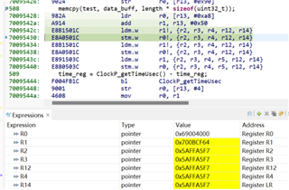
          Following your guidance, I try to understand the difference between 16*32bit and 17*32bit writing.

          I noticed that if write 16*32bit, the assembly code use R2, R3... to move "0x5affa5f7", as the 1st following picture shows. While write 17*32bit, the assembly code will call _aeabi_memcpy which move "0x5affa5f7" split by byte, as the 2nd and 3rd pictures show. 

          What is these meaning? I only should ues memcpy() to write less than 16*32bit? 


     For the Intel fpga PCIe core please refer to this link, https://www.intel.com/content/www/us/en/docs/programmable/683724/18-0/datasheet.html

    Thanks and BR

    Chunyang 


  • Hello Chunyang,

    ok, now it is starting to make sense. For some reason (not sure why), the memcpy implementation uses single-byte copy. According to some posts here in the forums this might be related to -O0 vs. -O3.

    With strongly ordered memory for 0x68... you should get invidiual PCIe transactions targeting a single byte each. The PCIe transaction will always address a 32-bit word, but there are byte enables for each of the four bytes, and there should be different byte enables set in each transaction.

    The Intel PCIe core should be able to correctly output these single byte writes. The Avalon-MM interfaces include byte-enable signals. This probably needs to be looked into by your FPGA colleagues. I suspect that there's something between the PCIe core and the signals shown in the pictures above (e.g. the documentation says the RXM interface is 64-bit or 128-bit wide and includes byte_enables). I believe this is outside the scope of this forum.

    The other question is whether it's a good idea to use "memcpy". A while ago I wrote this:

    With memcpy() the compiler might make optimizations that are only valid for "normal memory" (i.e. cacheable, no strong ordering). Whether that is possible depends on how you configure the 0x68000000 region in the MPU, and it depends on the memcpy() implementation.

    It turned out that the compiler / C-library didn't "optimize" but rather used a very simple byte-wise copy. The problem remains: You don't know how memcpy accesses memory, and thus memcpy is really only good for "normal" memory.

    If you want to transfer a "larger" amount of data you should try to generate larger bursts. If it is possible for your application you could mark that area of your PCIE0_DAT0 window (e.g. 0x69000000) as cacheable normal memory, and then use the CacheP functions to cause cache content to be written back / invalidated. This is going to be complicated.

    The alternative would be sticking with strongly ordered or device memory and manually coding the copy loop to generate larger bursts. I'd try volatile uint64_t* and verify in the disassembly how the data is being copied. For writing to the FPGA, device memory would be a lot faster that way. Reading is always going to be slow.

    Regards,

    Dominic