This thread has been locked.

If you have a related question, please click the "Ask a related question" button in the top right corner. The newly created question will be automatically linked to this question.

TMS570LS3134: Code exuction and ECC

Part Number: TMS570LS3134
Other Parts Discussed in Thread: NOWECC, UNIFLASH, HALCOGEN

Tool/software:

Hello,

I am currently trying to integrate ECC into my code but i had some question. I now that there is two type of execution first (XIP) where the code is directly executed from the Flash and the second where the code is copied to the RAM and executed from there but i wasn't able to found wich type the TMS570ls3134 is using. 

Also for the ECC when applied to the RAM I understood that when data is written to the RAM, ECC bits are calculated and put in the corresponding address and then when the data is read from the RAM a check is done using the caclulated ECC bits, in the case of an error it is corrected and in the case of two an interrupt is generated. But i didn't understand how it is working for the Flash i know that i have to generate ECC bits using nowECC but how does the check is done for the FLASH ?

Thank you for your help !

A.K

  • Hi A.K,

    I now that there is two type of execution first (XIP) where the code is directly executed from the Flash and the second where the code is copied to the RAM and executed from there but i wasn't able to found wich type the TMS570ls3134 is using.

    Here the code is directly executed from the flash.

    Also for the ECC when applied to the RAM I understood that when data is written to the RAM, ECC bits are calculated and put in the corresponding address and then when the data is read from the RAM a check is done using the caclulated ECC bits, in the case of an error it is corrected and in the case of two an interrupt is generated.

    You are totally correct about ECC handling in RAM.

    But i didn't understand how it is working for the Flash i know that i have to generate ECC bits using nowECC but how does the check is done for the FLASH ?

    Here the ECC is calculated and programmed into the corresponding ECC section in flash along with the code.

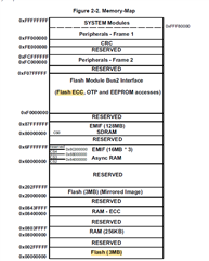
    So as highlighted in below pic, there will be two sections in the memory Flash and Flash ECC.

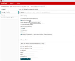
    The code should be programmed into the Flash and ECC of the corresponding code should be programmed into Flash ECC section. The CCS IDE or UniFlash will take care of this thing once we enabled the below check boxes.

    CCS IDE:

    UniFlash:

    After this if we enabled SECDED module then whenever the code fetching is happening then the corresponding code is validated with its ECC, if there is an ECC error then corresponding ESM flags or interrupts will get SET.

    For more details, please refer TRM and datasheet.

    --
    Thanks & regards,
    Jagadish.

  • Thank you for your answer,

    Is it possible to switch the execution type on this MCU? Switch from in place execution to executed in the RAM. 

    I saw this in the TRM document but I am not sure if it is an execution swap or just an address swap?

  • Hi Ahmet,

    As per my knowledge.

    This memory swap will swap the addresses of RAM and Flash only.

    I mean after performing this swap operation the flash address will be moved to the 0x08000000 and RAM address will be moved to the 0x00000000.

    But the text program still be in flash only which will be at 0x08000000, so doing this swap will not copy the flash code into the RAM addresses. This swap will just interchange the flash and RAM offset addresses.

    If you want to execute some part of the code into the RAM then i will suggest you refer below thread:

    (+) [FAQ] TMS570LC4357: Examples and Demos available for Hercules Controllers (E.g. TMS570x, RM57x and RM46x etc) - Arm-based microcontrollers forum - Arm-based microcontrollers - TI E2E support forums

    --
    Thanks & regards,
    Jagadish.

  • Thank you very much this cleared my interogrations about the execution in flash or RAM.

    About the ECC I saw that I already have the ECC parameter checked in the CCS option so when I flash my board the ECC bit are already put into the respective memeory space. To activate the SECDED module I took a look at the FEDACCTRL1 register.

    For the 3-0 bit any value other than 0x05 will activate the SECDED module. 

    In my program the SECDED module is enable by default, is this normal ?

    In the case where it is normal do I have to do something else except enabling ESM interrupts ?

  • Hi Jagadish,

    Thank you for your guidance. While implementing i had another question I generated a project using Halcogen and enabled Flash and RAM ECC's. In my startup function I now have enable Flash/Ram ecc and check Flash/RAM ecc functions. In the check flash function in diagnostic mode a single bit and multiple bits error are generated. The single bit error get corrected but the multiple bits one generate an abort. In the dabort.asm file since the abort is generated during the diagnostic mode the program continues but otherwise : 

    Like shown in the picture it says that it will "branch here forever" does that mean that in the case of a real life multiple bit error the program will get stuck ?

  • Hi Ahmet,

    Like shown in the picture it says that it will "branch here forever" does that mean that in the case of a real life multiple bit error the program will get stuck ?

    Yes, for multibit error it will stick at aborts forever. If you want, you can write software reset API required.

    Usually for multibit flash errors it would not be good to execute the code in flash that might cause unpredictable behavior in code execution.

    --
    Thanks & regards,
    Jagadish.

  • Hi Jagadish thanks for your answer.

    I would like to test the case where a real multibit error happen I thought about maybe trying to play around with the ECC bits before flashing it into the MCU but I don't know if it is possible. Also I have a watchdog enabled on my application, in the case where an abort happen because of the multibit does the MCU reset ? Do I have a way to know that a multibit caused this after the reset ?

    Thanks for your help !,

    A.K

  • Hi A.K.

    The simplest way to test multibit errors is using Diagnostic modes avaiable on the device.

    You can follow above method and can create the ECC errors. If you want code for this method then you can find it in the below SafeTI Diagnostic code:

    SAFETI_DIAG_LIB Driver or library | TI.com

    --
    Thanks & regards,
    Jagadish.

  • Hi Jagadish,

    I already tested my Flash with the diagnostic mode everything is working like expected, correction on single bit error and abort on multibit errors. But of what i saw during my test and in the dabort.asm file is that when the abort happen during the diagnostic mode the code dosen't really abort. What I want is to test it with a real case scenario and I want to see the program not comming back from the abort. 

    I tested this with the RAM and i was able to get the code to abort with a multi bit error and with a watchdog active I was able to get into the interrupt generated by it. I would like to test the same thing with the flash but i don't know if it is possible since the ECC bit are generated before flahsing the code. I saw that there where some command in nowECC to generate errors but due to a lack of time I wasn't able to check on it.

    Thanks for your help,

    A.K

  • Hi Ahmet,

    I would like to test the same thing with the flash but i don't know if it is possible since the ECC bit are generated before flahsing the code. I saw that there where some command in nowECC to generate errors but due to a lack of time I wasn't able to check on it.

    May be try fallowing procedure from UniFlash.

    1. Initially make sure you enabled Auto ECC generation option in UniFlash.

    2. Now select your .out file and Load image into the flash.

    3. Now export some part of the flash data to a bin file using UniFlash.

    4. Now open the exported binary into supported tool.

    5. Now alter the data bits as per the requirement.

    6. Once you altered the data bits in .bin file, now remove the Auto ECC generation option in UniFlash

    7. Also make sure you enabled Erase option as necessary sector only, previously it can be Erase complete flash but now we should select necessary sectors only.

    8. Now select the altered bin file in step-5 for flashing from UniFlash:

    Also give the appropriate load address from where we exported.

    Maybe it would be better to export and flash interns of sector sizes.

    9. As we disable Auto generation so for this data, maybe ECC will be considered as old ECC only. So, there should be ECC failures should occur for this new data.

    Try this method, have a look on below thread regarding more details about data export and flashing using UniFlash.

    (+) RM48L952: Flash EEPROM - Arm-based microcontrollers forum - Arm-based microcontrollers - TI E2E support forums

    --
    Thanks & regards,
    Jagadish.