This thread has been locked.

If you have a related question, please click the "Ask a related question" button in the top right corner. The newly created question will be automatically linked to this question.

AM263P4: AM263P4 SBL – Boot Address Discrepancy (0x80000 vs. 0x81000)

Part Number: AM263P4
Other Parts Discussed in Thread: UNIFLASH

Tool/software:

Dear TI Support Team,

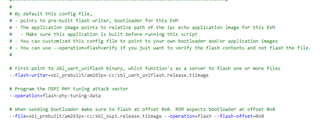
I’m trying to understand the expected behavior of the AM263P4 SBL when booting from OSPI flash. The documentation generally states that the appimage should be written to address 0x80000, but in practice, the image only boots correctly when placed at 0x81000.

A few inconsistencies raise questions:

  1. Most documentation references 0x80000, yet this does not work.
  2. TI’s own tools (Python-based and Uniflash) default to 0x80000, even though booting fails at that address.
  3. Uniflash does not allow writing to 0x81000, it fails citing an alignment issue, while uart_uniflash.py and uart_uniflash_gui.py allow setting the address manually.

Could you clarify the intended behavior? How is this supposed to work according to TI’s design? Understanding the expected workflow is crucial for resolving these inconsistencies.

Additionally, does this issue have any connection to the swap variant of the SBL? I understand that swap mode is not currently in use, but since it includes logic for selecting between variant A and B, could it be influencing the boot address in some way?

Looking forward to your clarification.

Best regards,

Jiri 

  • Hi Jiri,

    Apologies you had to face this confusion, Please me clarify the reason behind 0x80000 vs 0x81000

    For Flash access we are using the OSPI interface. Now OSPI interface also has a PHY which requires tuning data to be fed when working at high clock speed(>50Mhz)

    In the recent version of SDK we are flashing the tuning parameters at 0x80000 and then application flash at offset 0x81000.

    in older sdk we were not doing this. I understand that it is an inconvenient when changes come abruptly we are working on fixing that.

  • Most documentation references 0x80000, yet this does not work

    The latest documents have been updated, Please refer below.

    https://software-dl.ti.com/mcu-plus-sdk/esd/AM263PX/latest/exports/docs/api_guide_am263px/GETTING_STARTED_FLASH.html

    • TI’s own tools (Python-based and Uniflash) default to 0x80000, even though booting fails at that address.
    • Uniflash does not allow writing to 0x81000, it fails citing an alignment issue, while uart_uniflash.py and uart_uniflash_gui.py allow setting the address manually.

    This is a miss on our side, the Uniflash tool update went late as compared to SDK, so the latest uniflash tool will go live on ti.com with the issues fixed by next week.

    For now as a workaround the UART uniflash python script based flashing tool can be used:

    software-dl.ti.com/mcu-plus-sdk/esd/AM263PX/latest/exports/docs/api_guide_am263px/TOOLS_FLASH.html#TOOLS_FLASH_UART_UNIFLASH

  • Additionally, does this issue have any connection to the swap variant of the SBL? I understand that swap mode is not currently in use, but since it includes logic for selecting between variant A and B, could it be influencing the boot address in some way?

    Will need more info to comment on this.

  • We are not using swap variant of the SBL and I was not sure if it is related. Thats all. 
    But it make question: where (address) is second appimage? Where are some description about this in documentation?

  • Which version of the SDK uses "OSPI interface tuning data" and what it's mean? We are using the latest available version, 10.01.00.34 (as of today). What does this mean? It could be significant when we create our own board (different from CC/LP, therefore with our own modifications for proper boot). We need to maintain these modifications, which is difficult when we don't know what it is supposed to do. In other words, where is this documented?

  • The latest version of SDK used OSPI tuning data:

    In the file: C:\ti\mcu_plus_sdk_am263px_10_01_00_27\tools\boot\sbl_prebuilt\am263px-cc\default_sbl_ospi.cfg

    You can see the we send the OSPI tuning vectore:

    To read more about OSPI tuning:

    www.ti.com/.../spract2.pdf

  • Also for HW design guide line please refer this: 

    https://www.ti.com/lit/an/sprabj8c/sprabj8c.pdf

    But it make question: where (address) is second appimage? Where are some description about this in documentation?

    Please refer to TRM and also example documentation: software-dl.ti.com/.../bootseg_ip_working.html

  • OK, for me it was not clear that it is test pattern for the tuning. Because from the SDK documentation: 

      • Flash PHY tuning data : In certain NOR SPI drivers, for tuning the PHY, known data needs to be present in the flash. This is a fixed size (usually 128 bytes) array written to the last block of the flash. This check box needs to be ticked if you're flashing for the first time to the target so that this known data can be written to the flash.

    This mean, that it is not "tuning data" in meaning os board setting, but "tunnin data" as pattern to run tunning calibration on the SBL. And it is not on the "last block of the flash" but at address 0x80000. Correct?

  • How does this Python tool know that the correct address for this data is 0x80000 when, in the same tool, this address is the default for the app image? (I'm not analyzing this tool.)

  • The python tool takes the address based on the cfg file that is present in sdk:

    C:\ti\mcu_plus_sdk_am263px_10_01_00_27\tools\boot\sbl_prebuilt\am263px-cc\default_sbl_ospi.cfg

    this was updated in latest version of sdk.