This thread has been locked.

If you have a related question, please click the "Ask a related question" button in the top right corner. The newly created question will be automatically linked to this question.

C2000WARE-MOTORCONTROL-SDK: Motor control issues at high current and speed

Part Number: C2000WARE-MOTORCONTROL-SDK
Other Parts Discussed in Thread: DRV8350

We are trying to make a BLDC motor controller using the instaspin-FOC software with the fast observer. We are facing an issue where we start to lose control of the motor at higher Iq currents and higher speeds.

We notice the following when this happens:

  • The motor starts to lose efficiency.
  • There is an audible ringing that become present.
  • If we attempt to increase the current any further the motor becomes completely uncontrollable and trips the overcurrent of the DRV8350.

We are using the following:

Custom PCB:
F280049C
DRV8350RSRGZT
On Semi FDMC86520DC
0.5mOhm low side current sense with INA181A2IDBVR and low impedance 1.65V reference. +/- 66A
Phase + bus voltage measurements of 95.3kOhm and 4.99kOhm with 0.1uF. Giving a cut-off of 335.82 Hz

Motor:
We are using a BLDC drone motor with 42 pole 36 slot motor
35mOhm resistance
~35uH inductance
100kV
To apply a load to the motor we are using a propeller so we cannot decouple the speed and current.

Power
Battery cells outputting ~48V

Software
We are basing our software off lab is08 since we wanted to use overmodulation. This was after SDK 3.2.0.0 so we have the flux library and have adjusted it.
The problem starts to happen when we command over 30A Iq. In order to reach these levels we have had to use overmodulation.

We have looked over the forms a lot to try find solutions we came across this post that seems to have similar issues to us. But it doesn’t seem like a solutions was never reached https://e2e.ti.com/support/microcontrollers/c2000-microcontrollers-group/c2000/f/c2000-microcontrollers-forum/976708/c2000ware-motorcontrol-sdk-sensorless-foc-speed-problems-with-tms320f280049c We have tried many of the recommendations in this thread.

Things we have tried:

Add a function that adjusts the inductance as the current increases. This didn’t help too much.

We have tried using it by directly controlling the Vq in order to eliminate any instability in the current control loop.

We have tried disabling the single current sensor current reconstruction to make sure it is not that causing issues.

We have tried a few different PWM frequencies.

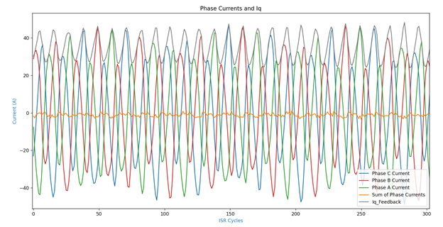
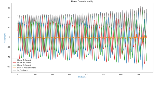
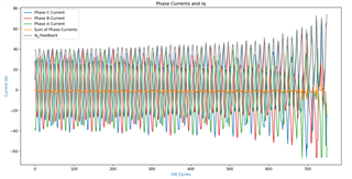
While trying to dig into the problem we have noticed that the ADC readings of the phase currents do not seem to line up. It appears that one of the currents is always shifted up or down from the others. We are not sure if this is what is causing the problem or if it is a result of another problem.

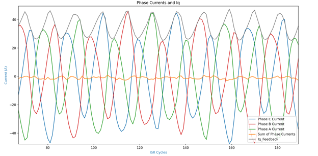
Here is an image of the phase currents plot near to the point where we loose control of the motor (These images are taken at an electrical frequency of ~1062Hz and a PWM frequency of 17kHz):

Phase currents near point of loss of control

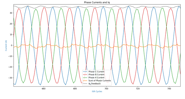
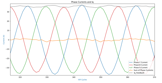
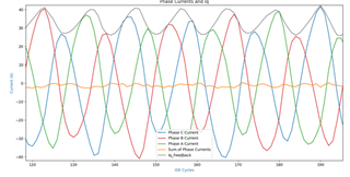
Zoomed in just before we loose control:

Zoomed in phase current miss-alignment

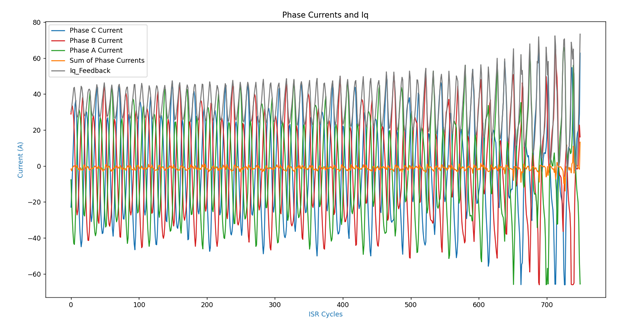
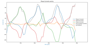
Zoomed in on where we loose control:

Zoomed in during loss of control

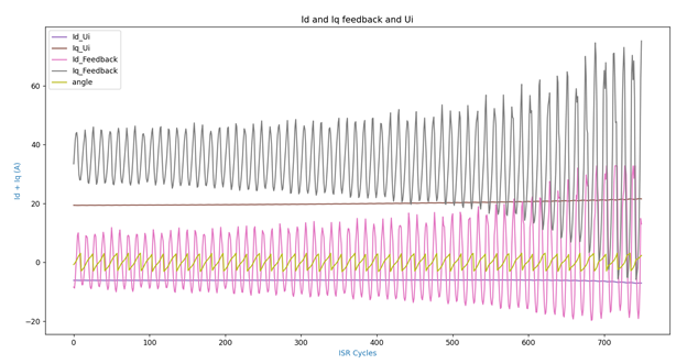
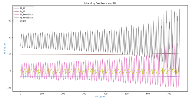
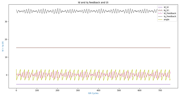
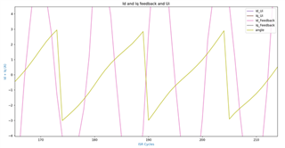
We also have a more detailed view of some of the Id and Iq values, both the Ui and feedback values. The electrical angle is also included in this:

Iq + Id feedback and Ui values

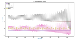
Zoomed in on the electrical angle it appears that the line is not strait at this point even though there is no reason that the speed would be changing that quick.

Motor electrical angle

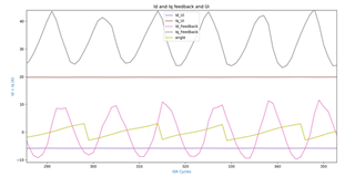
Zooming in on the Iq and Id values makes it appear that the current control loops are not responding to the feedback values. Changing the gains also didn’t help things. Also we have tried to drive with only the Vq value and we were still having this problem:

Zoomed in Iq+Id with Ui values almost unchanging while feedback changes rapidly

We are looking to get the motors working at higher powers without any efficiency or stability problems. We can provide any further information that you need and will try any suggestions you have to try get us to a solution. At the moment we are just stuck on what the best avenue is to try get the motors working as quick as possible.

Best Regards.

  • You might have a look at the link below to add the patch library (fluxHF_coff.lib or fluxHF_eabi.lib ) into the project for high speed.

    https://e2e.ti.com/support/microcontrollers/c2000-microcontrollers-group/c2000/f/c2000-microcontrollers-forum/921747/tms320f280049c-fast-estimator-questions

  • We are using SDK 3.2.0.0 which already includes the fluxHF settings. I think this was added back in 3.01.00.00.

    We are using the following settings:

    //! \brief Defines the scale factor for the flux estimation
    //! the default value is 1.0f, change the value between 0.1f and 1.25f
    //!
    #define USER_EST_FLUX_HF_SF                 ((float32_t)(0.12f))
    
    
    //! \brief Defines the scale factor for the frequency estimation
    //! the default value is 1.0f, change the value between 0.5f and 1.5f
    //!
    #define USER_EST_FREQ_HF_SF                 ((float32_t)(1.0f))
    
    
    //! \brief Defines the scale factor for the bemf estimation
    //! the default value is 1.0f, change the value between 0.50f and 1.25f
    //!
    #define USER_EST_BEMF_HF_SF                 ((float32_t)(0.75f))

  • We have tried disabling the single current sensor current reconstruction to make sure it is not that causing issues.

    What do you mean above? Did you try to run the motor at the same higher speed with a light load? So we try to know the issue is from the high speed or high speed with heavy load.

  • In svgen_current.h we removed cases where SVGENCURRENT_ONE_PHASE_MEASURABLE was active. The code is below. However, this problem exists even with the default code in svgen_current.h.

        //define compensation mode
        if(Va_avg > Vlimit)
        {
    
            obj->compMode = SVGENCURRENT_TWO_PHASE_MEASURABLE;
            obj->ignoreShunt = SVGENCURRENT_IGNORE_A;
    
            if(Vb_avg > Vc_avg)
            {
                obj->Vmid = SVGENCURRENT_VMID_B;
            }
            else
            {
                obj->Vmid = SVGENCURRENT_VMID_C;
            }
    
        }
        else
        {
            if(Vb_avg > Vlimit)
            {
    
                obj->compMode = SVGENCURRENT_TWO_PHASE_MEASURABLE;
                obj->ignoreShunt = SVGENCURRENT_IGNORE_B;
    
                if(Va_avg > Vc_avg)
                {
                    obj->Vmid = SVGENCURRENT_VMID_A;
                }
                else
                {
                    obj->Vmid = SVGENCURRENT_VMID_C;
                }
    
            }
            else if(Vc_avg > Vlimit)
            {
                obj->compMode = SVGENCURRENT_TWO_PHASE_MEASURABLE;
                obj->ignoreShunt = SVGENCURRENT_IGNORE_C;
    
                if(Va_avg > Vb_avg)
                {
                    obj->Vmid = SVGENCURRENT_VMID_A;
                }
                else
                {
                    obj->Vmid = SVGENCURRENT_VMID_B;
                }
            }
            else
            {
                obj->compMode = SVGENCURRENT_ALL_PHASE_MEASURABLE;
                obj->ignoreShunt = SVGENCURRENT_USE_ALL;
            }
        }

    Yes, we have run the motor at high speed with light load with no problem.

    Unfortunately we can not run at at low speed with high load since we are using a propeller to load it up so the load is directly proportional to the speed.

  • Seems like the issue is from the current sensing, please try below two steps to see what happens

    1. Don't enable the over modulation to run the motor at high speed.

    2. Enable the over modulation, but limit the USER_MAX_VS_MAG_PU is lower than (0.57f).

  • We have tried as you suggested and we found that the problem still happens even with Over Modulation turned off. I will include the captures of this for completeness.

    OVM turned on and USER_MAX_VS_MAG_PU (0.56f):

    OVM turned on and USER_MAX_VS_MAG_PU (0.5f):

    OVM turned off:

    No OVM Iq = 36A 30 secondsNo OVM Iq = 36A 30 seconds

    Also to note with most of these with the same Iq reference the motor will run for a short amount of time (about 20 seconds and then fail) for example 20 seconds before the last captures this was taken at the same Iq. However, it still appears that there is something wrong with the currents not lining up and over time this problem just gets worse until it fails.

    No OVM Iq = 36A 10 seconds

  • We also did some test with the same phase currents but lower speeds (we have a larger propeller) and the issues don't seem to show up.

    Here are the plots with an Iq ref of 36A (Same as is failing on previous plots):

  • 1. What's the peak to peak current at this state? Is the peak to peak current over than the maximum sampling value of the ADC?

    2. Did you try to use the different Kp and Ki of the speed PI controller for low speed and high speed? And change the gains of the PI controller for torque current as well?

    1. Before it messes up the peak to peak current is ~72A. We have a range of 132A. When it starts run away the current approaches 132A peak to peak. However if we stop it from running away this should not be a problem.
    2. We have tries using different PI values for the torque controller. We are not using the speed controller at the moment and are just directly controlling the current. We have also tried to directly control the Vq value directly, bypassing the control loops and had the same results.
  • Do you have the Ls/Ld/Lq vs. Current curve of the motor? If the inductances change significantly with the current, the motor mathematics model will be not correct for motor control with FAST estimator. You have to change the motor parameters online for the FAST estimator to calculate the rotor angle correctly.

  • We do not have a curve for the motor. However, we have made our own mathematical curve for it. The curve has adjustable parameters that we are able to change. We have tried many values for the curve to try approximate any changes that do happen as the current increases without any noticeable improvements.

  • You have to get the current-inductance curve from the motor manufacturer. The FAST estimator of InstaSPIN-FOC is sensitive to the motor parameters (Rs, Ld and Lq).

  • We are going to work on getting these parameters, it may take a little while. We will follow up when this is done.

  • OK. Let's close this thread first. You can reply with a post again if have any further update.