This thread has been locked.

If you have a related question, please click the "Ask a related question" button in the top right corner. The newly created question will be automatically linked to this question.

TMS320F280049C: InstaSPIN Instability at High Speed - 280049C & DRV8353

Part Number: TMS320F280049C
Other Parts Discussed in Thread: MOTORWARE, DRV8353, LAUNCHXL-F280049C, BOOSTXL-DRV8320RS

Hi There,

The Problem Summary:

We're seeing instability (high and spurious current draw) at high speeds. Enabling of over-modulation appears to exacerbate the issue. Our control system is torque only, and there are no outer loops currently while we understand this issue. Finally, the instability appears to be worst when using higher speed / lower inductance electric-machines.

Background:

We're developing our own Inverter using the TMS320F280049C & DRV8353S and are using Sensorless FOC control by leveraging InstaSPIN & FAST.  The hardware is being developed in house and has been through deep verification. See the list at the end of this post for what we have confirmed.

Some details of the system:

  • 30VDC - 60VDC operation
  • 30ARMS maximum continuous current per phase
  • 1kW maximum continuous power
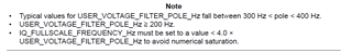
  • 3x current sense and 3x voltage sense, voltage filter pole set to 353Hz as per SPRUHJ1I.
  • DRV8353S gate driver & current shunt amplifiers
  • 20kHz PWM & control frequency

Our inverter operates with several motors of different characteristics from 60uH & 50mR up to 200uH & 150mR. All these motors are PSMS and run up to ~750Hz electrical maximum.

Issue Details:

As previously mentioned, we're seeing instability at high speeds, starting at 550Hz to 600Hz electrical. The issue exists on multiple motors where lower inductance & higher speed motors seem to be worse effected. The instability exhibits with large current draw and loss of a sinusoudal current waveform, i.e. spurious spikes of current far above those expected. The motors are stable under maximum loads, confirmed over temperature and speed during detailed verification of the power electronics. The issue only presents when we're operating at high speed and low/no loads, i.e. when the motor back-EMF is close to DC bus voltage.

Strangely, our prior usage of Motorware & 28069 processors showed excellent performance with even higher speed and lower inductance machines (800Hz electrical, 27uH & 11mR), so we're at a bit of a loss why we're seeing instability. It could be the hardware, which has evolved in this time, however without documentation on expected hardware performance and FAST being black-box, we cannot find any causes for the instability.

After a lengthy investigation in our firmware (and hardware, see below), we found that including a recent FluxHF patch into our project and tuning some arbitrary coefficients greatly improved performance of the control system, however it is concerning that we're now tuning a black-box and the ramifications of such tunings are unclear.

We did also notice that increasing the USER_VOLTAGE_FILTER_POLE_Hz from 354Hz to ~750/1000Hz (without hardware change...) improved stability, which was made us consider the FluxHF patch in the first place. This was not considered a fix as I know this software filter must align with the hardware filtering and chalked this up to dumb luck, but it did suggest an issue with rotor position estimation.

Finally, the documentation for InstaSPIN (SPRUHJ1I - October 2021) does not appear to line with with the recent Motor Control SDK, and artefacts (USER_IQ_FULL_SCALE_FREQ_Hz) no longer exist, but are referenced as being important. I generally find TI documentation to be excellent.

QUESTION 1: Can you please confirm the behaviour of instability is normal with aforementioned motors & frequencies? If this is not normal, I would appreciate any guidance on hardware verification we can perform to isolate the cause.

QUESTION 2: I was hoping you could provide some information about how to best tune the FluxHF coefficients, why this is required, and what each coefficient is intended to do? Essentially, we need some context for why these need to be changed.

QUESTION 3: This may sound like a stupid question, but is it expected that we tune these FluxHF coefficients on a per-motor basis, or are these more related to the characteristics of the Inverter & sensing hardware? There is no documentation I can find on these coefficients, hence the question.

QUESTION 4: When will the InstaSPIN user guide & lab documentation be updated for the most recent Motor Control SDK? There are several references to now removed characteristics, e.g. USER_IQ_FULL_SCALE_FREQ_Hz and the relationship to USER_VOLTAGE_FILTER_POLE_Hz. Further the FluxHF coefficients are not explained. Considering they are oftenly recommended for use on these forums, it sets off a bit of an alarm bell.

We're happy to provide further design details, verification, scope plots if required, although we are limited in a public forums with closed source designs.

Thanks for your help,

-Doug

HW verification & HW-SW integration performed:

  1. Run through the various InstaSPIN labs upto lab 10.
  2. Current Sensing signals to the TI uC's from the DRV8353 are as expected and within expected accuracy.
  3. Voltage Sensing signals to the TI uC's & their filtering are appropraitely designed based on provided documentation and is performing as expected (lines up with theoretical).
  4. ADC results are free from noise & are scaled appropriately. We're seeing very low noise on ADCs while switching.
  5. Complete verification of power electronics and their meeting of the DRV8353 specification
  6. Confirmed ADC's SoC configuration is correct
  7. Confirmed FOC ISR is running with minimal delay and without processor time starvation.
  8. Hardware designed and layed out carefully on a high-layer-count board with attention paid to power & small signals, grounding, bypassing, etc.
  • If the overmodulation is disabled or the USER_MAX_VS_MAG_PU is limited to (0.57), is the instability issue still existing at high speed?

    QUESTION 1: Can you please confirm the behaviour of instability is normal with aforementioned motors & frequencies? If this is not normal, I would appreciate any guidance on hardware verification we can perform to isolate the cause.

    What's the rated speed/frequency of the motor? What high speed do you want to run with the motor?

    QUESTION 2: I was hoping you could provide some information about how to best tune the FluxHF coefficients, why this is required, and what each coefficient is intended to do? Essentially, we need some context for why these need to be changed

    The FluxHF is for the low inductance and low BEMF constant motor, and only need to tune USER_EST_FLUX_HF_SF according to the USER_MOTOR_RATED_FLUX_VpHz, set USER_EST_FLUX_HF_SF to a small value if USER_MOTOR_RATED_FLUX_VpHz is low.

    QUESTION 3: This may sound like a stupid question, but is it expected that we tune these FluxHF coefficients on a per-motor basis, or are these more related to the characteristics of the Inverter & sensing hardware? There is no documentation I can find on these coefficients, hence the question.

    As Q2, it is related to the motor.

    QUESTION 4: When will the InstaSPIN user guide & lab documentation be updated for the most recent Motor Control SDK? There are several references to now removed characteristics, e.g. USER_IQ_FULL_SCALE_FREQ_Hz and the relationship to USER_VOLTAGE_FILTER_POLE_Hz. Further the FluxHF coefficients are not explained. Considering they are oftenly recommended for use on these forums, it sets off a bit of an alarm bell.

    Not special update for motor control SDK since the FAST estimator is the same, just IQmath format is used for motorWare, floating point for motorControlSDK.

  • Hi,

    Thanks for your quick reply. And apologies for the obvious omissions of information.

    If the overmodulation is disabled or the USER_MAX_VS_MAG_PU is limited to (0.57), is the instability issue still existing at high speed?

    Yes, the issue exists at high speed with over-modulation disabled (via USER_MAX_VS_MAG_PU set to 0.5). It was less severe though occuring less frequently and with recoverable spikes in current, i.e. before the over-current protections of our inverter kick in.

    What's the rated speed/frequency of the motor? What high speed do you want to run with the motor?

    We're seeing instability around the 550Hz to 600Hz electrical frequency. Our motor is designed to run upto ~750Hz electrical absolute maximum.

    The FluxHF is for the low inductance and low BEMF constant motor, and only need to tune USER_EST_FLUX_HF_SF according to the USER_MOTOR_RATED_FLUX_VpHz, set USER_EST_FLUX_HF_SF to a small value if USER_MOTOR_RATED_FLUX_VpHz is low.

    Do you have some numbers for what should be considered low inductance, low BEMF constant? I have no idea what FAST considers low inductance, so numbers are critical.

    The motor we're having the most trouble with has a rated flux in Vp/Hz of 0.0288, is this low enough for us to need FluxHF?

    I'm asking the above as I'm concerned our hardware design is not providing FAST what it needs and tweaking FluxHF is merely hiding a bigger problem.

    A piece of information I forgot to relay in my initial post was that the instability was significantly worse when I decreased the hardware filter pole frequency from its original ~750Hz down to ~350Hz (47nF to 100nF). The inclusion of FluxHF was the only way we could make the system operate above ~350Hz electrical with the 350Hz filter pole.

    The change to the hardware filter pole was done based on InstaSPIN documentation, which suggests that the electrical frequency of the motor can be higher than the pole. Is this correct?

    Thanks for your help,

    -Doug

  • Do you have some numbers for what should be considered low inductance, low BEMF constant? I have no idea what FAST considers low inductance, so numbers are critical.

    Most of the drone, or other low voltage high current motors are the low inductance motor, the d-axis and q-axis inductance are about 100uH~1mH

    The motor we're having the most trouble with has a rated flux in Vp/Hz of 0.0288, is this low enough for us to need FluxHF?

    Yes. The FluxHF can be used for any motors, just need to change USER_EST_FLUX_HF_SF. If USER_EST_FLUX_HF_SF equals to 1, the lab will be as the original lab without FluxHF.

    The change to the hardware filter pole was done based on InstaSPIN documentation, which suggests that the electrical frequency of the motor can be higher than the pole. Is this correct?

    Correct. Recommend that pole frequency is between 300Hz and 1000Hz, use a higher pole frequency for a high speed motor and high switching frequency. And the pole frequency must be calculated correctly according to the hardware filter.

  • Yes. The FluxHF can be used for any motors, just need to change USER_EST_FLUX_HF_SF. If USER_EST_FLUX_HF_SF equals to 1, the lab will be as the original lab without FluxHF.

    Out of interest, what would happen if using Motorware (last update 2017) with such a low inductance motor? In my experience there was no need for FluxHF. Again, I ask not to point the finger at TI, but to try and understand why we're seeing instability, ideally to gain some understand of which FAST requirements our hardware/firmware is not meeting.

    Correct. Recommend that pole frequency is between 300Hz and 1000Hz, use a higher pole frequency for a high speed motor and high switching frequency. And the pole frequency must be calculated correctly according to the hardware filter.

    300Hz to 1000Hz is a rather large range, where we saw more stable operation at 750Hz than 350Hz, however the InstaSPIN documentation suggests the lower frequency pole should be used (SPRUHJ1I page 243):

    The same example goes on to mention that 300Hz to 400Hz is ideal and that the upper limit is related to the maximum frequency of the motor divided by 4, albeit with #defines that no longer exist in Motor Control SDK:

    Ultimately, I'm struggling to understand what FAST requires without clear and consistent information.

    Most of the drone, or other low voltage high current motors are the low inductance motor, the d-axis and q-axis inductance are about 100uH~1mH

    Thank you for the confirmation of the inductances we would expect to need FluxHF to drive without issue.

    I get the sense that we need to use some TI development kits with our firmware ported to get confirmation that our hardware & firmware is correct. I can't see another way of confirming we're meeting FAST's requirements without more information.

    This isn't what I would consider "good engineering" as this exercise involves trying to reverse engineer the requirements of a black-box...

  • Out of interest, what would happen if using Motorware (last update 2017) with such a low inductance motor?

    It's fine for using MotorWare. It's just a bug for F28004xC with FAST in MotorControlSDK.

    The same example goes on to mention that 300Hz to 400Hz is ideal and that the upper limit is related to the maximum frequency of the motor divided by 4, albeit with #defines that no longer exist in Motor Control SDK:

    It's for typical motor in motorWare. The low inductance motor needs to use a higher PWM frequency, so it's better to use a high pole frequency as well.

    It's just an option for checking the setting values, not necessary for the final code. You can still refer to InstaSPIN-FOC and InstaSPIN-MOTION User's Guide for the FAST in motorControlSDK.

    https://www.ti.com/lit/spruhj1

  • It's fine for using MotorWare. It's just a bug for F28004xC with FAST in MotorControlSDK.

    I don't understand. Previously you implied that the 28069F & MotorWare was identical to 280049C & MotorControlSDK except for IQmath vs. floating point math, and now there is a bug with the F28004xC with FAST. Is there an errata on this?

    Again, I don't really care if there a bug and there needs to be a workaround. I only care about improving our confidence in the stability in the system for reliability & safety reasons.

    It's for typical motor in motorWare. The low inductance motor needs to use a higher PWM frequency, so it's better to use a high pole frequency as well.

    It's just an option for checking the setting values, not necessary for the final code. You can still refer to InstaSPIN-FOC and InstaSPIN-MOTION User's Guide for the FAST in motorControlSDK.

    I understand this, but with FAST being black box, I would like more information on what is expected. Should I be measuring the pk-pk waveform of the voltage sense signals during 50% duty cycle, the amplitude of BEMF at a particular electrical frequency?

    My concern is borne from the improvement to FASTs performance at high speeds when I changed the voltage filter pole to a value that is much higher than it should be, at least based on what can be inferred from InstaSPIN documentation.

    Ultimately, what I'm looking for here is confirmation that my voltage filters are appropriately designed. What is the best strategy for testing this? Spinning a motor at much higher voltages and speeds than normal to confirm FAST performs with decent margin? Is this test actually proving we have margin, or are there other factors than electrical frequency that affect FAST?

  • Is there an errata on this?

    That's why need to add the FluxHF library for high speed low inductance motor. We have validated this library on some high speed low inductance motor.

    Should I be measuring the pk-pk waveform of the voltage sense signals during 50% duty cycle, the amplitude of BEMF at a particular electrical frequency

    You should select a right voltage sampling circuit to achieve a better resolution. The voltage filter 

    What is the best strategy for testing this? Spinning a motor at much higher voltages and speeds than normal to confirm FAST performs with decent margin? Is this test actually proving we have margin, or are there other factors than electrical frequency that affect FAST?

    We recommend the related parameters for FAST estimator that could be fine for most of the typical motor. Some special motors should still need to tune these parameters, it's difficult to provide a specific value and equation for all of the motors, this is always a engineering question for a specific design.

    You may provide the detailed motor specification to us, so we can try to find a similar motor for validation in lab, or you can provide a motor to us as talked with your sales.

  • You should select a right voltage sampling circuit to achieve a better resolution. The voltage filter 

    Can you please provide details of how to do this?

    Based on the InstaSPIN user guide and your previous responses, the filters need to be design to satisfy two requirements:

    1. To low-pass the PWM waveforms into the "average" voltage applied to a phase, pushing for a lower frequency pole.

    2. To ensure the BEMF waveform is correctly represented, pushing for a higher frequency pole.

    The quantitative aspects of these requirements are largely undefined. Further, it is unclear how sofisticated FAST is in compensating for PWM ripple or what the acceptable BEMF waveform gain & phases are, so which of these two requirements do I favour?

    Some special motors should still need to tune these parameters, it's difficult to provide a specific value and equation for all of the motors, this is always a engineering question for a specific design.

    I can completely understand this, but you have iterated my question for me: It is an engineering question for a specific design, but we do not have the information to answer that question, i.e. details of what FAST requires to function properly.

    I'm happy to provide more details of Motors and our hardware filters if that allows TI to provide guidance for the design of filters & the tuning for motors?

    Thanks for your continued responses and help.

  • As mentioned above, the 300~400Hz is recommended to a typical filter frequency for most of the motors. A higher filter frequency (<800Hz) is better for the high speed motor with a high PWM frequency. There is no a specific equation to set the specific relationship between the filter frequency and the motor maximum speed and PWM frequency.

    Did you try to run your motor on a TI EVM kit? The example lab has been validated on a drone motor with a high speed (1000Hz) and 50A on the LAUNCHXL-F280049C + BOOSTXL-DRV8320RS.

  • Did you try to run your motor on a TI EVM kit? The example lab has been validated on a drone motor with a high speed (1000Hz) and 50A on the LAUNCHXL-F280049C + BOOSTXL-DRV8320RS.

    Not yet sorry, I have not had any spare time to requisition these boards and do an investigation. I will report back when I get a chance.

  • Could you please post the schematic and user.h to enable use the setting parameters you did? And post some measured current waveform to help us to understand the issue?

    Did you try to tune the PI regulator for speed and current? Use the different gains for low speed and high speed?

    All these motors are PSMS and run up to ~750Hz electrical maximum.

    The 750Hz is the maximum target electrical frequency you want? What's the maximum running frequency now without issue? And the peak/RMS phase current at this state?

  • Hi There,

    Thank you for coming back to us yet again, but I have run out of time and will be away for several months. I suspect we will resume this item in a few months when I return but thank you for your help provided.

    Regards,

    -Doug

  • Ok. Let's know if you have any questions about the motor control with C2000 and InstaSPIN-FOC. Thanks!