This thread has been locked.

If you have a related question, please click the "Ask a related question" button in the top right corner. The newly created question will be automatically linked to this question.

F28335 Unable to Program and XRS Periodically Asserting Low

Other Parts Discussed in Thread: TMS320F28335, TPD8F003

I have a newly designed board featuring the F28335.  I have been unable to program it thus far, getting either of these errors:

Error connecting to the target:
(Error -501 @ 0x0)
The built-in scan-path length measurement failed.

Error connecting to the target:
(Error -233 @ 0x0)
The JTAG IR and DR scan-paths cannot circulate bits, they may be broken.

I have discovered that the XRS' reset pin is periodically going low, approximately every 4.1 ms for a duration of 16 us.  I see that this pin can double as a watchdog output, but I haven't even been able to program the chip once so far, the closest I got once was what appeared to be clearing the Flash.

We did have a power supply issue at first that lead the +3.3 V to rise to almost +5 V at times.  That has since been fixed, but perhaps the F28335 is toast?

I have verified that the XDS100v3 that I'm using still can program our other Stellaris based project.  I'm using CCS v5.

Any ideas what might be wrong here?

  • I have some more information.

    First, I now found the thread XRS pin 80 of F28335 pulled low which says this 217 Hz reset pulse on XRS is normal and should go away when the JTAG is connected.  It is ambiguous if this means when the cable itself to the emulator is connected or when the debug command is sent from CCS.  Either way, when I connect the JTAG cable or when I try pressing the debug button, the XRS pulses do not stop.  I am still getting the error:

    The value is '-501' (0xfffffe0b).
    The title is 'SC_ERR_TEST_MEASURE'.

    The explanation is:
    The built-in scan-path length measurement failed.
    The built-in scan-path reliability tests cannot be
    performed without knowledge of the scan-path length.
    Try specifying the scan-path lengths in the command-line
    options or board configuration file of this utility or debugger.

    The program I'm using is the SYS-BIOS hello world example program hello_TMS320F28335.  It builds ok and I can run it ok using the F28335 controlCARD on the experimenter's kit.

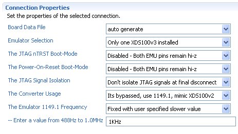
    I have also tried adjusting the clock rate of the JTAG down to 1 kHz.  My settings are shown below.  I have the XDS100v3 mimicing XDS100v2 as appropriate - these settings are the same that I successfully use on my LMS3S9D96 project.

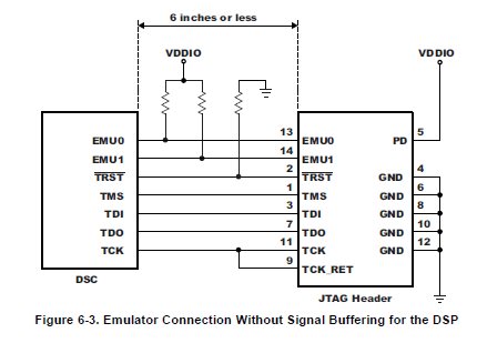
    I have checked continuity to my power pins to their respective +3.3 V and + 1.9 V regulated supplies, and the grounds.  I have done resistance checks on the JTAG connections as well.  I do have TPD8F003 EMI/ESD protection in the JTAG paths (as I do in my Stellaris project with no problem) as well as some Littel LC03-3.3 EFT/Surge protection devices, which are new for this project.  As per page 123 of the F28335 manual, my JTAG has the pull-ups and pull-downs shown:

    2.2 k pull-down on TRST' and 4.75 k pull-up on EMU0 and EMU1, with an additional 10 kOhm pull-up to +3.3 V on TMS.

    The crystal seems to be operating correctly at 32 MHz as well. 

    The boot mode is (A15, A14, A13, A12) = 1111, "Jump to Flash."  We did have a power supervisor TPS3828-33 in the circuit just as in the F28335 controlCARD, but it has been temporarily removed when we were tracing down the XRS pulse origin.

    The full results from the "Test Connection" button in the ccxml file is:

    [Start]

    Execute the command:

    %ccs_base%/common/uscif/dbgjtag -f %boarddatafile% -rv -o -F inform,logfile=yes -S pathlength -S integrity

    [Result]


    -----[Print the board config pathname(s)]------------------------------------

    C:\DOCUME~1\USER\LOCALS~1\APPLIC~1\.TI\1989394224\
        0\0\BrdDat\testBoard.dat

    -----[Print the reset-command software log-file]-----------------------------

    This utility has selected a 100- or 510-class product.
    This utility will load the adapter 'jioserdesusbv3.dll'.
    The library build date was 'Apr  1 2013'.
    The library build time was '23:55:08'.
    The library package version is '5.1.73.0'.
    The library component version is '35.34.40.0'.
    The controller does not use a programmable FPGA.
    The controller has a version number of '4' (0x00000004).
    The controller has an insertion length of '0' (0x00000000).
    This utility will attempt to reset the controller.
    This utility has successfully reset the controller.

    -----[Print the reset-command hardware log-file]-----------------------------

    The scan-path will be reset by toggling the JTAG TRST signal.
    The controller is the FTDI FT2232 with USB interface.
    The link from controller to target is direct (without cable).
    The software is configured for FTDI FT2232 features.
    The controller cannot monitor the value on the EMU[0] pin.
    The controller cannot monitor the value on the EMU[1] pin.
    The controller cannot control the timing on output pins.
    The controller cannot control the timing on input pins.
    The scan-path link-delay has been set to exactly '0' (0x0000).

    An error occurred while hard opening the controller.

    -----[An error has occurred and this utility has aborted]--------------------

    This error is generated by TI's USCIF driver or utilities.

    The value is '-501' (0xfffffe0b).
    The title is 'SC_ERR_TEST_MEASURE'.

    The explanation is:
    The built-in scan-path length measurement failed.
    The built-in scan-path reliability tests cannot be
    performed without knowledge of the scan-path length.
    Try specifying the scan-path lengths in the command-line
    options or board configuration file of this utility or debugger.

    [End]

    This is the first time we've made a board with the F28335 soldered on directly rather than using a controlCARD (but we have completed a project with the Stellaris chip on a custom board ok). 

    What should I check next?

  • We replaced the F28335 and it can now program and run successfully.  I can only conclude that the power supply issue we saw earlier had exceeded the absolute ratings long enough to ruin the F28335.

    Oddly enough, the test connection at 1 kHz still didn't work but the default 1 MHz did.

    Also, to clarify, the watchdog low pulses on XRS' only stop well into the debug sequence when the JTAG begins clearing memory.  The XRS seems to stay in this state until the JTAG cable is disconnected.

  • Andrew,

    Thank you for posting your solution.  I am glad you got it working.

    Regards,

    Adam