Instanspin FOC SDK V2.01:
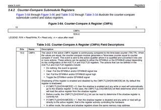
Configuring EPWM module CMPB for compare UP/DN counts loaded direct into period registers fails to load any value into CMPB of any configured generator.
Configuring dead band generators for mode 2 ACH/ACL complementary (Fig.18-8) is not possible via DBCTL[POLSEL] as typedef enumerations were missing epwm.h or hw_epwm.h.
Note: I attempted to add enumerations below but polarity bits S2, S3 when made 2, 3 respectively caused load FED mode register bits to change. There are overlaps in the register control function calls that would be less confusing to separate (mode/polarity) register loads into two functions. The shift/mask enumeration values differ for the complementary dead band mode 2, versus mode 4 so the older C2000 firmware function call is not working as it should for mode 2 dead band control. Closest DBCTL register can be set (0x000A) from calls below.
//*****************************************************************************
//
//! Values that can be passed to EPWM_setDeadBandDelayPolarity(),
//! EPWM_setDeadBandDelayMode() as the \e delayMode parameter.
//
//*****************************************************************************
typedef enum
{
    EPWM_DB_RED = 1, //!< DB RED (Rising Edge Delay) mode
    EPWM_DB_FED = 0, //!< DB FED (Falling Edge Delay) mode
	EPWM_DB_AHC = 1, //!< DB mode AH is Complementary
	EPWM_DB_ALC = 0  //!< DB mode AL is Complementary
} EPWM_DeadBandDelayMode;

//*****************************************************************************
//
//! Values that can be passed to EPWM_setDeadBandDelayPolarity as the
//! \e polarity parameter.
//
//*****************************************************************************
typedef enum
{
    EPWM_DB_POLARITY_ACTIVE_HIGH = 0, //!< DB polarity is not inverted
    EPWM_DB_POLARITY_ACTIVE_LOW  = 1,  //!< DB polarity is inverted
	EPWM_DB_POLARITY_ACTIVE_HIGH_COMPLMNT = 2, //!< DB polarity is High Complementary
	EPWM_DB_POLARITY_ACTIVE_LOW_COMPLMNT = 1 //!< DB polarity is Low Complementary

} EPWM_DeadBandPolarity;
1. Why has the Instaspin SVM module code been embedded into ROM when it was shown in TRM and stated to be exposed for designer inspection?
2. Why is the CMPB register not being loaded with any count values via the SVM module in ROM given code below?
3. How can a (pair) of symmetric complementary (EPWM-A/B drive signals) ever be configured via ROM or firmware without configuring dead band mode 2 relative to SDK InstaSPIN FOC?
4. Why has C2000 register enumeration values (epwm.h etc..) not kept consistent binary/hex values that relate to TRM figures and register layouts? Instead C2000 firmware development has made it impossible for quick designer review using the TRM without entering CCS debug register view.
        // setup the Counter-Compare Control Register (CMPCTL)
        EPWM_setCounterCompareShadowLoadMode(obj->pwmHandle[cnt],
                                             EPWM_COUNTER_COMPARE_B,
                                             EPWM_COMP_LOAD_ON_CNTR_ZERO);

        // setup the Action-Qualifier Output B Register (AQCTLB)
        EPWM_setActionQualifierAction(obj->pwmHandle[cnt],
                                      EPWM_AQ_OUTPUT_B,
                                      EPWM_AQ_OUTPUT_HIGH,
                                      EPWM_AQ_OUTPUT_ON_TIMEBASE_UP_CMPB);
		//
        EPWM_setActionQualifierAction(obj->pwmHandle[cnt],
                                      EPWM_AQ_OUTPUT_B,
                                      EPWM_AQ_OUTPUT_LOW,
                                      EPWM_AQ_OUTPUT_ON_TIMEBASE_DOWN_CMPB);

                                             // setup the Dead-Band Generator load mode Register (DBCTL)
        EPWM_setDeadBandDelayMode(obj->pwmHandle[cnt], EPWM_DB_AHC_RED, true); //EPWM_DB_RED
        EPWM_setDeadBandDelayMode(obj->pwmHandle[cnt], EPWM_DB_AHC_FED, true);

        // select EPWMA as the input to the dead band generator
        EPWM_setRisingEdgeDeadBandDelayInput(obj->pwmHandle[cnt],
                                             EPWM_DB_INPUT_EPWMA);

        // setup DBCTRL mode/polarity for H/L symmetric complementary dead band.
        EPWM_setDeadBandDelayPolarity(obj->pwmHandle[cnt],
                                      EPWM_DB_AHC,
                                      EPWM_DB_POLARITY_ACTIVE_HIGH_COMPLMNT);

        // setup the Dead-Band Rising Edge Delay Register (DBRED)
        EPWM_setRisingEdgeDelayCount(obj->pwmHandle[cnt], HAL_PWM_DBRED_CNT);

        // setup the Dead-Band Falling Edge Delay Register (DBFED)
        EPWM_setFallingEdgeDelayCount(obj->pwmHandle[cnt], HAL_PWM_DBFED_CNT);


