This thread has been locked.

If you have a related question, please click the "Ask a related question" button in the top right corner. The newly created question will be automatically linked to this question.

Lowest active mode current/power for MSP430FR5969

Other Parts Discussed in Thread: MSP430G2553, MSP430FR5969, ENERGYTRACE, MSP-FET

I have been trying to operate MSP430FR5969 launchpad at its lowest current with VLO (~10 kHz) and MCLK divider 32. So effectively it is running at 312.5 Hz. When the board is externally powered (1.9 V), it draws about 48 uA. Note that all J13 jumpers to debugger removed, Super cap is not used (J2 and J11). All port pins are are in the default high impedance state. Having achieved 0.4 uA current consumption for MSP430G2553 launchpad before at 1.5 kHZ MCLK and 1.9V, for MSP430FR5969 with 100 uA/MHz rated current consumption, I would expect a much lower current drawing(0.03 uA + minimum current leakages). Curious, whether has somebody tried or have any idea about the minimum power consumption at the lowest clock in active mode for MSP430FR5969?  

Code is below.

Thanks!

#include <msp430.h>

void main(void)

{
WDTCTL = WDTPW + WDTHOLD; // Stop watchdog timer

CSCTL0_H = CSKEY >> 8; // Unlock clock registers

CSCTL5 &= ~LFXTOFFG;
CSCTL2 = SELM__VLOCLK | SELA__VLOCLK | SELS__VLOCLK;

do
{
CSCTL5 &= ~LFXTOFFG;
SFRIFG1 &= ~OFIFG;
} while (SFRIFG1&OFIFG);

__bis_SR_register(SCG1 + SCG0 + OSCOFF);

CSCTL3 = DIVM__32 | DIVA__32;
CSCTL4 = HFXTOFF | SMCLKOFF | LFXTOFF;

CSCTL0_H = 0;

/*M5CTL0 &= ~LOCKLPM5;

P4DIR = 0xFF;
P4OUT = 0x00;

P1DIR = 0xFF;
P1OUT = 0x00;

P2DIR = 0xFF;
P2OUT = 0x00;

P3DIR = 0xFF;
P3OUT = 0x00;

PJDIR = 0xFF;
PJOUT = 0x00;*/

for (;;)

{
_delay_cycles(100);
}
}

  • >So effectively it is running at 312.5 Hz
    Better you make sure that it is so indeed - enable clock output on MCLK pin and measure it.
  • Thanks for the suggestion. On oscilloscope both MCLK and ACLK were read at 327 Hz. Slight variation from 312.5 Hz should be expected as VLO is not precise. I also tried with EneryTrace. It shows VLO, ACLK, MCLK, FRAM, active mode runtime percentages as 100%, 100%, 10.4%, 100%, 10.4%. All other modules at 0.0%. Not sure how accurate the EnergyTrace readings though.
  • >Not sure how accurate the EnergyTrace readings though.
    Runtime current measurement shall be considered precise enough. Especially if you make comparative measurements. How did you measure 0.4uA on G-series? Also with Energytrace?

    You shall measure current ofinfinite low power mode(s) - to test against leakage. Sometimes it could be PCB dirt or deffective capacitor that consumes current ;)
  • For current measurement an external power supply was connected in series with a multimeter in uA range. All jumpers to the debugger and super capacitor were removed.  As for the EnergyTrace, debugger jumpers were in place, and no measurements were taken from the multimeter. EnergyTrace was done only for MSP430FR5969, not for MSP430G2553(not having a MSP-FET interface, only the USB)

    It seems a good idea to try in low power modes for testing leakages. At the the moment I don't have the board with me, and can give it try tomorrow. I tried with another MSP430FR5969 board, had similar results with slight difference.


    Thanks!

  • Why dont you use multimeter with jumpers removed.

  • I tried with LPM3 using example code (msp430fr59xx_lpm3_02.c, commented P1OUT ^= BIT0;), and it drew 0.5 uA when externally powered while debugger and super cap jumpers were removed. That matches approximately with datasheet LPM3 rated current value (0.4 uA), eliminating the possibility of PCB leakage currents.

    I mean I didn't use the multimeter when EnergyTrace was done with debugger (Jumpers connected, and consuming current is much higher anyway due to debugger circuit). But multimeter was used in series when the debugger and super cap jumpers removed with external power supply.

    Thanks!

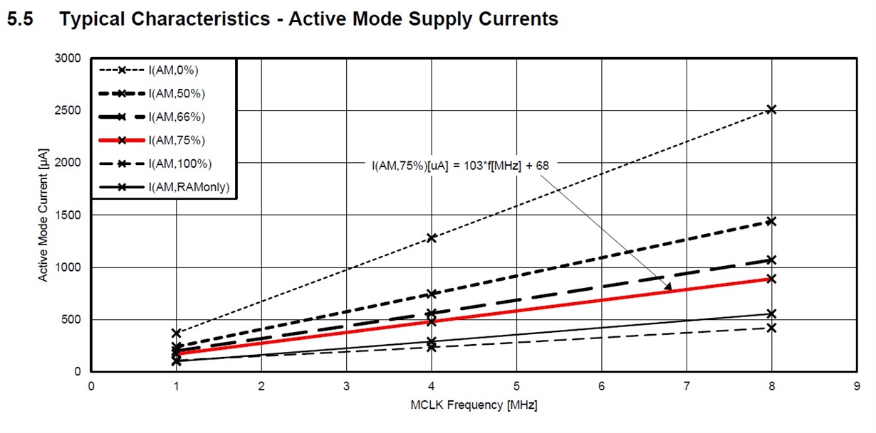
  • It seems like MSP430FR5969 has a considerable active mode minimum current independent of the frequency (68 uA at 75% FRAM hit ratio). This minimum current may be due to FRAM in comparison to MSP430G2553. Am I understanding this correct?

  • exactly, it seems that the curves do not cross Y axe at 0µA

**Attention** This is a public forum