Dear Support team
We are using the UCC21750 to drive the Wolfspeed C3M0021120K in a frequency range of 10kHz up to 250kHz. The driver supply voltages are +15V and -4V according to the ideal requirements of the MOSFET.
The supply voltage of the driver is derived from a constant current source with two shunt regulators generating the +15/-4V. The constant current is 50mA which limits the maximum power supplied to the driver IC to 50mA*(15-(-4V))=950mW. We designed the power supply like this to ensure operating conditions are within the Power Ratings defined in the datasheet of the UCC21750 on page 6. It also helps to maintain the Safety Limiting Values defined under point 6.8.
With this design, the maximum frequency is limited to around 130kHz. At higher frequencies, the 50mA current is exceeded and the undervoltage lockout turns the driver off.
However, according to the thermal characteristics mentioned in Point 6.4, the junction to board thermal resistance is only 32,9K/W. Based on this, a total driver dissipation of e.g. 2 watts and a board temperature of 50°C, the junction temperature would be 2*32,9+50=115.8°C which is well below the maximum junction temperature of 150°C.
Is it possible to operate the driver above the maximum permitted power dissipation of 985mW defined in point 6.5 and the supply current of 61mA defined under point 6.8 as far as the junction temperature stays below 150°C?
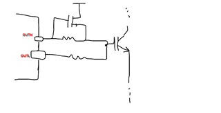
As an alternative, we could boost the driver output using a separate driver IC like Ixys IXDN614. The useage of bipolar output transistors as shown in the datasheet may be too slow for our application.
Regards
Frank Schoelch