This thread has been locked.

If you have a related question, please click the "Ask a related question" button in the top right corner. The newly created question will be automatically linked to this question.

Using N channel FETs instead of P channel FETs in BQ78PL116

Other Parts Discussed in Thread: BQ78PL116, BQ78PL114

Hi all,
I'm encountering problems of massive heating, when using BQ78PL116,

one of the obvious solutions is using more FETs in parallel,

in the application notes TI is using P channel FET, which for my voltage and current are very expensive and have small variety.


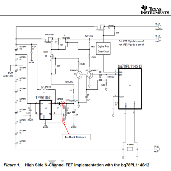
can someone offer a change of schematic to N-Channel FETs for DSG FET and CHG FET?

thanks

  • Hi,

    We have a preliminary NFET circuit that you can use on the high side.

    See below. This circuit works well with the bq78PL114/116 because of the active balancing.

    You can start with Feedback Resistor values of 13.3Mohm and 162kohm

    Regards,

    Ben

  • Dear Mr. Sarpong,

    thanks for the help,

    I was examining this schematic and overall understood it.

    I am worried about one issue:


    when we tested our PCB, first we tried to dedicate one mosfet for charge and 3 for discharge.

    as a result (since they have a common drain), the CHG mosfet was much hotter !!

    we came to a conclusion that the number of mosfet for charge or discharge should be equal, so the heat will dissipate equally.

    is this conclusion a right conclusion?

  • Hi Ran,

    Could let us know the configuration of your FETS? Are they in Series  or Parallel?

    Your earlier post mentioned that they were in Parallel. Of this is the case, then the CHG and DSG Paths are separate and you should ensure you have the right sized FETs for the CHG and DSG Currents.

    If they are in Series, then having an equal number of CHG and DSG FETs will be ideal.

    Ben


  • Dear Mr. Sarpong

    thanks for the reply.

    my FET arrangement is exactly as in the EVM.  a pair P-channel FET in parrallel for DSG, common drained with a pair of P- channel FET in parrallel  for CHG.

    I know that what you say is true (about having an equale number of FETs for CHG and DSG), because we saw it happens.

    and I have 2 questions for you (just to verify...):

    1. when actually discharging or actually charging (if we follow the EVMs Schematic), both CHG FET and DSG FET will open? since we are using a single P+ for load and charge). if so, does it comes from the chipset's software or hardware?
    2. what ever calculation for the number of  DSG FET (regarding RDs(on) reletively to DSG currents), should be implemented on CHG FET as well, even if CHG current is lower by multiplications?
      in that case, can I include the CHG FET in the current calculations?
      (example:
      for 30A DSG current and 5A charge current, I would usually use 6 FETs for DSG and 1 FET for CHG, If I understand correctly, can we use 3 FETs for DSG and 3 FETs for CHG in this case?)

    thanks for your help and fast replys!


  • Hi Ran,

    Note that the NFET circuit I showed earlier has a configuration where the Charge and Discharge FETS are in Parallel. This allows you to use a relativel inexpensive PFET for the Charge Path .

    To Answer your Questions:

    1) The FET Controls come from the part. The PL114 senses the Overcurrent conditions and opens the FETS accordingly.

    2) If you have the CHG FET and DSG FETs in Series, then yes, you will need to include the RdsOn for the CHG FET in the calculations..