Hi team,


This thread has been locked.
If you have a related question, please click the "Ask a related question" button in the top right corner. The newly created question will be automatically linked to this question.
Hi team,


Hi Lillian,
Q1. - I need to discuss internally. Will update you in 1 or 2 days.
Q2.
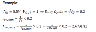
Calculate the situation of Vin=3.63V and Vout=3.329V: VIN=3.63V, VOUT=3.329V => Duty= 3.329V/3.63V= 0.917 fsw_max=1/(ton_min)*0.917=1/(0.075us)*0.917=12.22MHz>4MHz Is it conceivable that it can be set to any value from 1 to 4MHz? And in the "Example" case, it can only be set to the range of 1~2.67MHz?
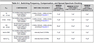
Yes that's right. With your specific conditions Fsw_ max is 12.22MHz. For this device & application conditions, Fsw can be set between 1.8-MHz to 4-MHz.
And for the example, Fsw_ max is 2.67MHz. Fsw can be set between 1.8-MHz to 2.67-MHz & not 4-MHz.
Regards,
Febin
Hi Febin,
Thanks for your reply, hope you newest update for Q1.
Thanks
Lillian
Hi Lillian,
Q1.
Looks like we have not validated and characterized this particular condition. I am trying to find out if we have some simulation data.
I hope to update you early next week.
Regards,
Febin
Hi Febin,
Can you give the calculation method when Vin =3.63V and Vout=3.2V (the condition of Vin >Vout +1V is not met)?
We hope that Vout guarantees an accuracy range of 3.00V ~ 3.329V, and Iout>0.65A. The inductor is 3.3uH, ±20%, 2.3A(L), 2.0A(T), DCR=55mΩ±20%, 40MHz. Within what range can Iout ensure the output accuracy reaches 3.00V ~ 3.329V?
Thanks
Lillian
Hi Lillian,
Can you give the calculation method when Vin =3.63V and Vout=3.2V
Calculation method for what?
Regards,
Febin
Hi Lillian,
In general, you may use the following formula:
VOUT= VIN - [IOUT*(Rdson_HS + Rdcr_L)] assuming load current is constant.
Just to clarify, if they are going to operate continuously in 100% mode. Wouldn't it be better to choose an LDO?
Regards,
Febin
Hi Febin,
We are currently reviewing the feasibility of TPS62441RQ replacing TPS62410DRCR. We would like to further confirm that when the usage conditions do not meet Vin>=Vout +1V, even if the off time of the high-side switch is greater than 30ns (without entering 100% duty mode), the following Vfb accuracy cannot be guaranteed?

Thanks
Lillian
Hi Lillian,
Can you ensure it will not enter 100% mode? I think it will enter 100% mode when Vin<Vout +1V
Regards,
Febin
Hi Febin,
We found from the d/s:

Made the following calculations
f=2.25Mhz → T=444ns;
D= Vout/Vin =3.329/3.63 =91.71%
off time = T*(1-D) = 36.8ns (> 30 ns)
Therefore, it is considered that it has not entered 100% Duty-Cycle mode.
In your reply you believe that Vin<Vout +1V will enter 100% Duty-Cycle mode. Therefore, in order to achieve Vout =3.329V, Vin must be >4.329V to ensure an output accuracy of 1%, right?
Hi Lillian,
Sorry for the delay. I will come back to you in one or two days.
Regards,
Febin
Hi Lillian,
In your reply you believe that Vin<Vout +1V will enter 100% Duty-Cycle mode. Therefore, in order to achieve Vout =3.329V, Vin must be >4.329V to ensure an output accuracy of 1%, right?
As per the designer of the device, it is recommended to have the 1V delta to ensure device is not in 100% mode.
The Vfb accuracy of +/-1% is valid for this condition.
off time = T*(1-D) = 36.8ns (> 30 ns)
This is the off-time calculated for your specific application condition.
As the datasheet says, if the minimum Toff_HS of typically 30ns reaches, skips switching cycles and enter 100% mode.
It is just the typical value, it could be in 100% before or after 30ns.
This is the reason to recommend the 1V delta between Vin & Vout to restrict the duty cycle to ensure that the device will not enter the 100% mode.
Please let me know if we need to have a call to discuss this topic and close this issue. I think this would be better.
Regards,
Febin